


Before making
1.It may be difficult to make Micropede by using desktop 3D printer like Replicator2
All the parts of Shellmo that include Micropede, have been designed with the assumption that of they would be prepared with Shapeways (Strong and Flexible Plastic) . To begin with, the user might encounter the problem related to the precision of the parts, due to the fact that Micropede includes many elements, such as the gear and the bearing. In other words, it is conceivable that in such printer as Replicator 2 that needs the removal of the support of the parts, the mechanical elements do not function fully. In order to enable it to work fully, quite a lot of trials and errors would be required. To put it in another way, we can say that it is a challenge-worthy module .
2.You need a little skill for assembling Micropede
For instance, even if one had obtained the parts by using Shapeways, etc, their assembly requires some skill and perseverance. In particular, if one is making them with the parts of Shapeways, it requires the work I call "smoothing", using the Tester. Moreover, Pin being an extremely small part, connecting Pin and Leg with pinchers requires dexterity . That is to say, it is a module that is worth making.
3.If you completed to assemble, there are problems to use it.
As I have also written about it here, there are many problems in the operation of Micropede. What often happens during its running is that its feet come off the Pin. However, I believe that this problem can be solved, if an improvement of the shape of the Pin and Leg could be devised. Let me add that when one makes it walk on a totally flat surface, such as the desk top, it can do so comparatively steadily. In other words, one can say that it is a module with room for hacking.
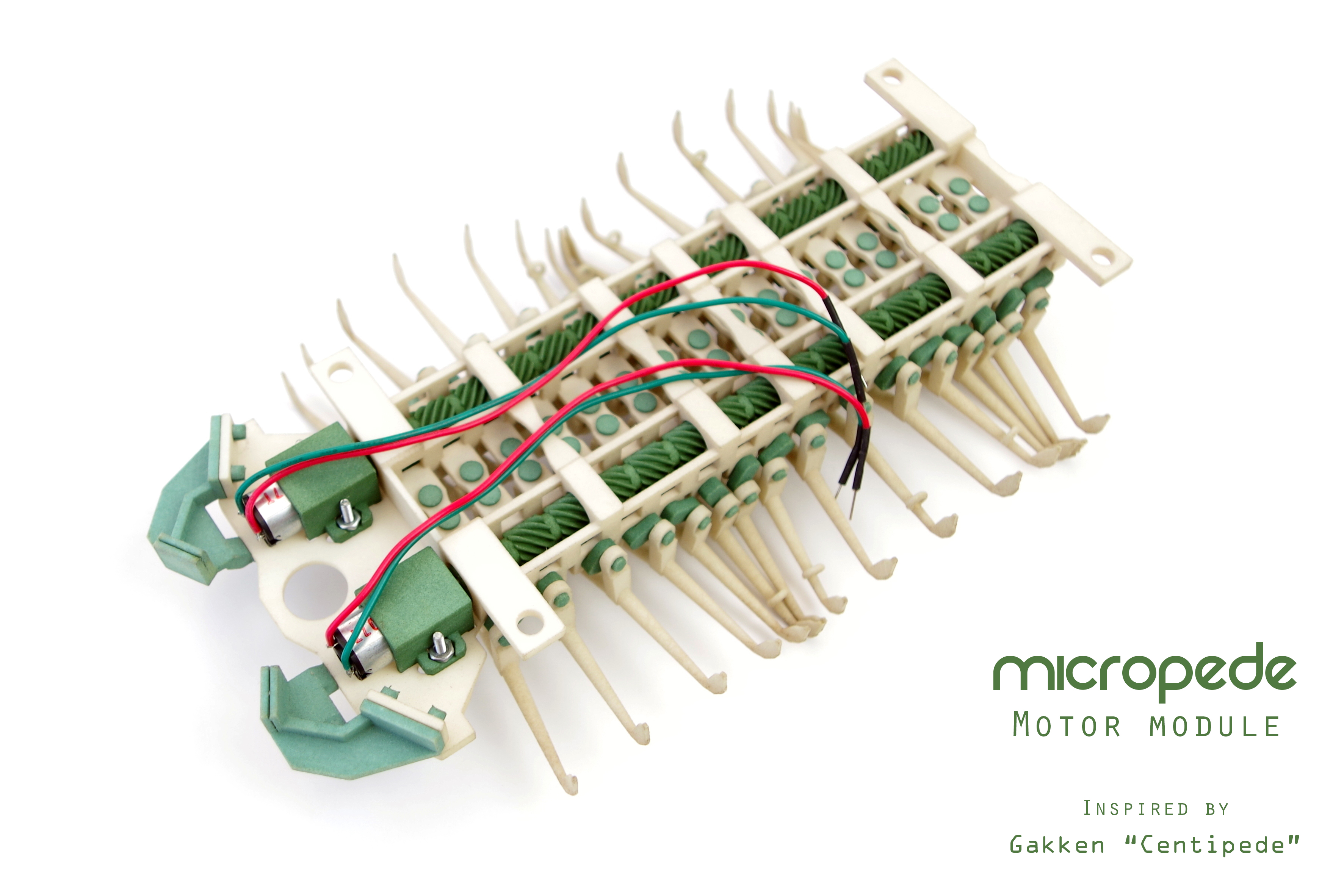
Process
1.Prepare Parts and Tools
2.Assemble Cranks and Shafts
3.Assemble Legs
4.Install Gearmotors
5.Walking Test
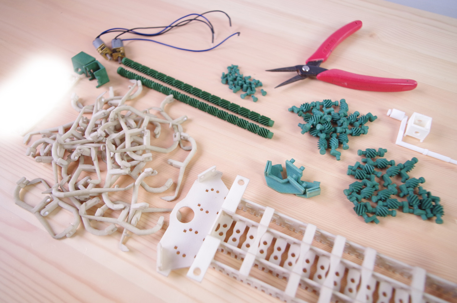
1.Parts and Tools
3D printed parts:
Download All:Skp Stl Obj ShapewaysObj
If you will use Shapeways, please order Micropede_#1 to #10. View shop
MP_LEGnormal_V001*24 Shapeways
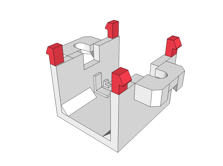
MP_MOTORCOVER_V001*2 Shapeways
Please make "PIN" and "LEG" more than you need.
You should make about 36(32+4spares) Pins and Legs total.
Because, it is fragile and easy to lose.
If you want
Jaws(Left and Right) for flexible sensor
Linkrod for connecting to Shell "Cambria"
Electric parts:
100:1 Micro Metal Gearmotor "HP" *2 Pololu RobotShop
Jumpwires *4 Sparkfun
Mini Breadboard *1 Sparkfun
AABattery *4 Sparkfun
AABatteryHolder *1 Sparkfun
*If you can buy 4xAAA Battery holder, you should buy it also.(I can't find it on Sparkfun)
Other parts:
- Pololu Micro Metal Gearmotor Mounting Bracket (Extended-Pair)*1 Sparkfun RobotShop Pololu
This parts is compatible with MP_MOTORCOVER.But, this includes screws and nuts.
So,I recommend you to buy this also. (At least, You need 4 screws and 4 nuts.)
Tools:
Pliers
Nipper
Solder iron and Solder
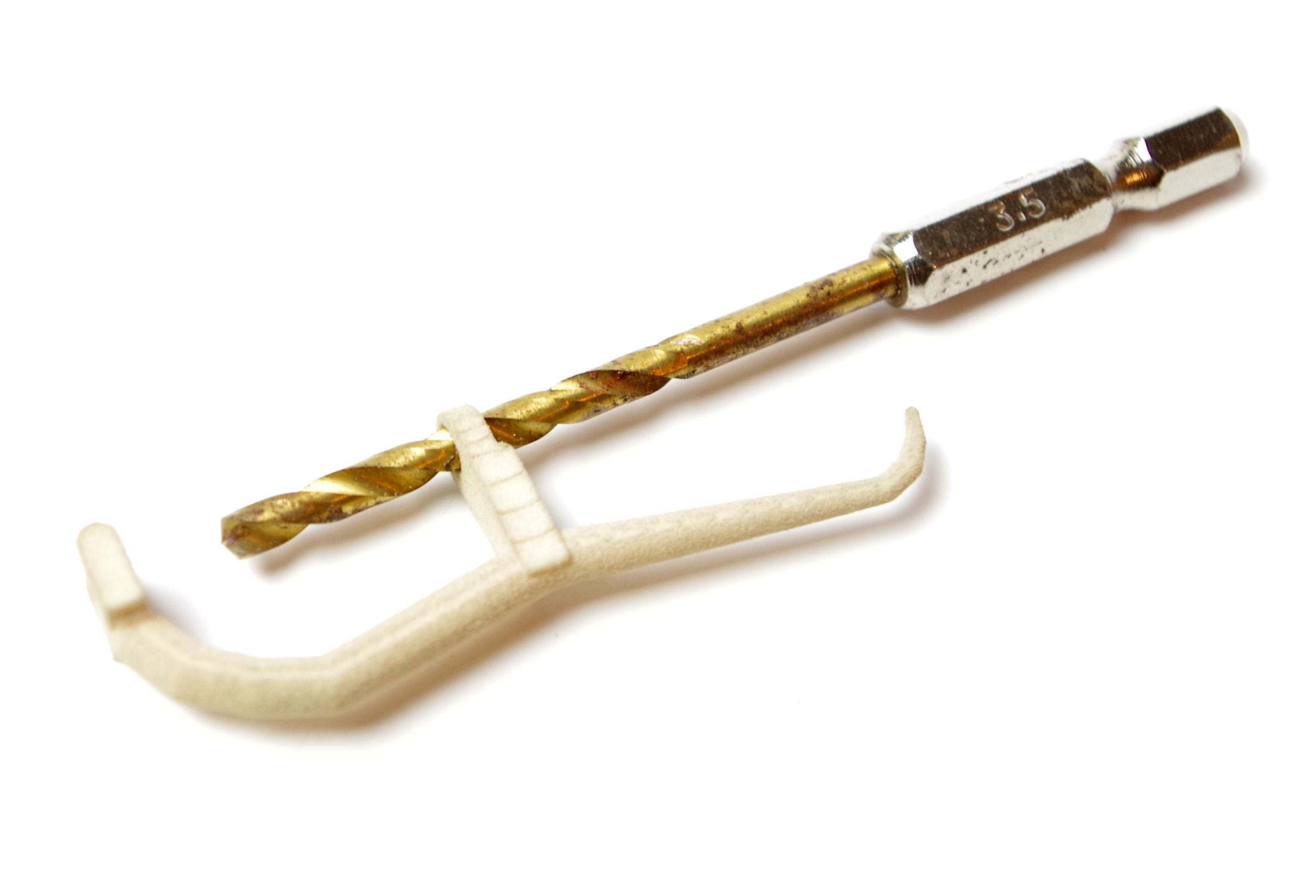
Drill and Drillbit(φ3.5mm)
Screwdriver(for screw of motorcover)
Adhestive tape
Regarding the cleaning of the parts.
When one uses the parts which were obtained by 3-D printing with Shapeways, one needs to wash away the powder remaining in the gaps of the parts. For Micropede, the powder tends to remain particularly in the gaps of the gear of the shaft and the crank, as well as in the bearing portions of the Chasis and the Shafts, so focusing on these places, wash the powder away, using a brush or something similar.
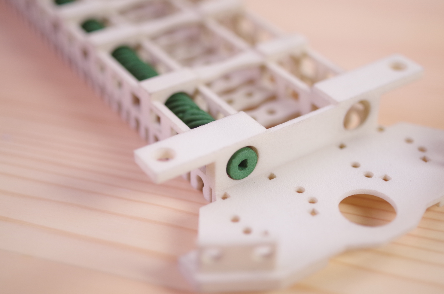
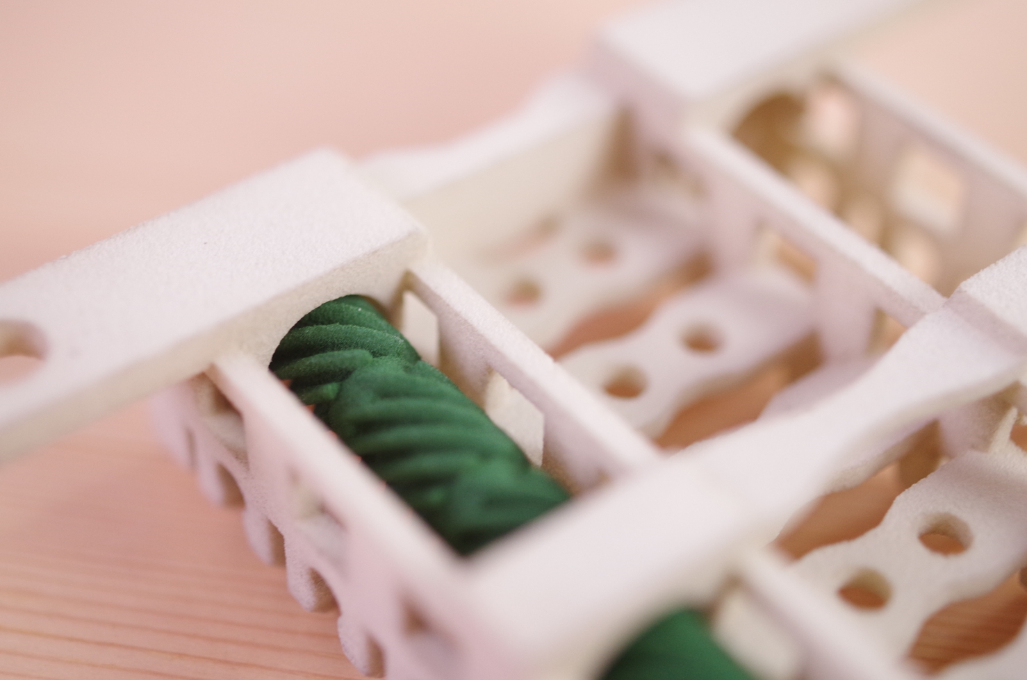
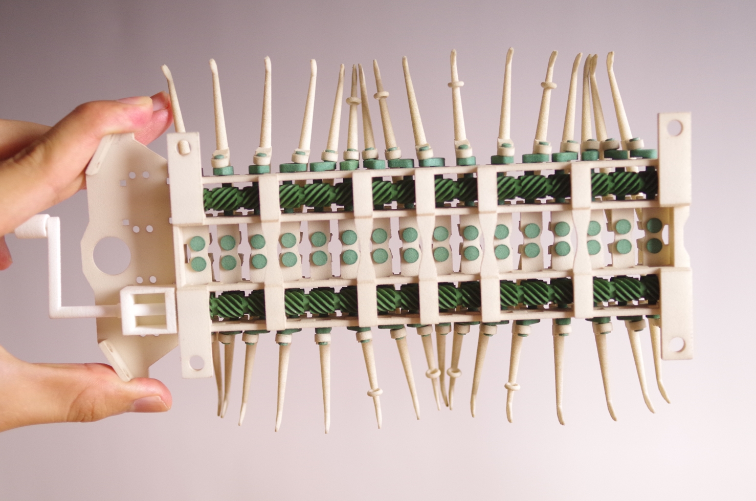
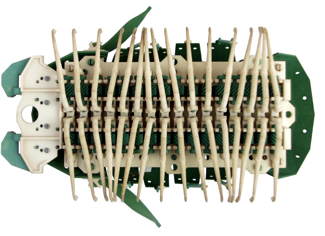
2.Assemble Cranks and Shafts
Assemble Shaft
There is a difference between the Shaft on the right and that on the left. Referring to the photograph, mount the Shafts that are facing the same way.
Start with one Shaft. While it is being done, insert the rear part of the Shaft into the bearing portion of the Chassis.
Assemble crank
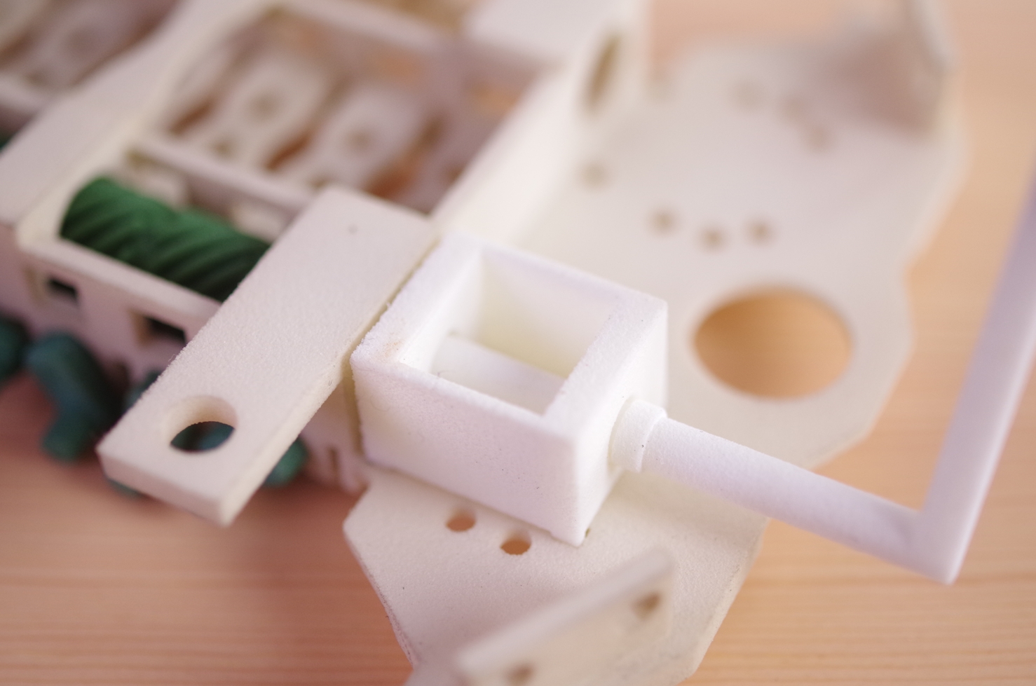
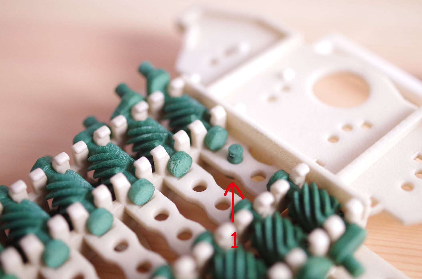
Please turn the Chassis inside out. The right Crank differs from the left one. Referring to the photograph, place the Crank on top of the Chassis. Mount the Crank so that the gear of the Shaft and that of the Crank mesh with each other. Starting with the inside, fit the axis of the Crank (1). next insert that on the outside(2). As shown in the video, shift the angle of the rotation of the Cranks by 45 degrees for each. Please begin by mounting the four Cranks.
The method of dealing with the Outer Layer
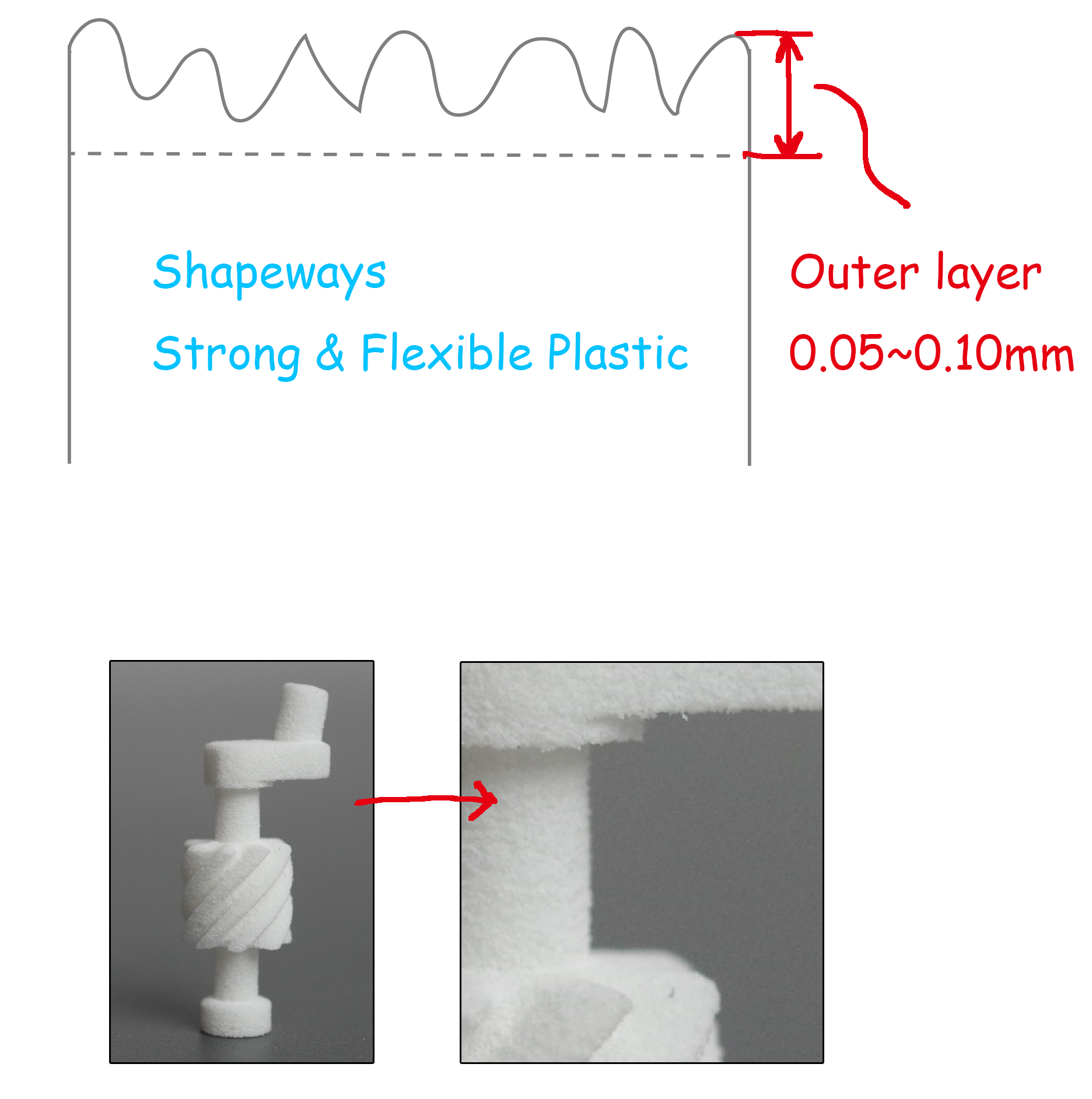
In the case of obtaining it by the 3-D printing, using Shapeways, a layer whose thickness is approximately 0.05 - 0.10mm, a layer that tends to be abrasive, will form on the surface. I call this the outer layer. In making the Micropede that requires precise movements, this outer layer constitutes a problem.
As its countermeasure, the measurement that will provide just the right distance after abrasion has been determined. This enables the mechanism to move smoothly which is made possible by the abrasion made on the outer layer intentionally during assembling, thereby the interior that withstands the abrasion, is exposed.
I call this work "smoothing".
In the Micropede, such parts as its Cranks and Legs, etc, feel heavy, but they have been set up to move lightly by means of "smoosing" by the Tester and Gear Motor, etc. This will be described later.
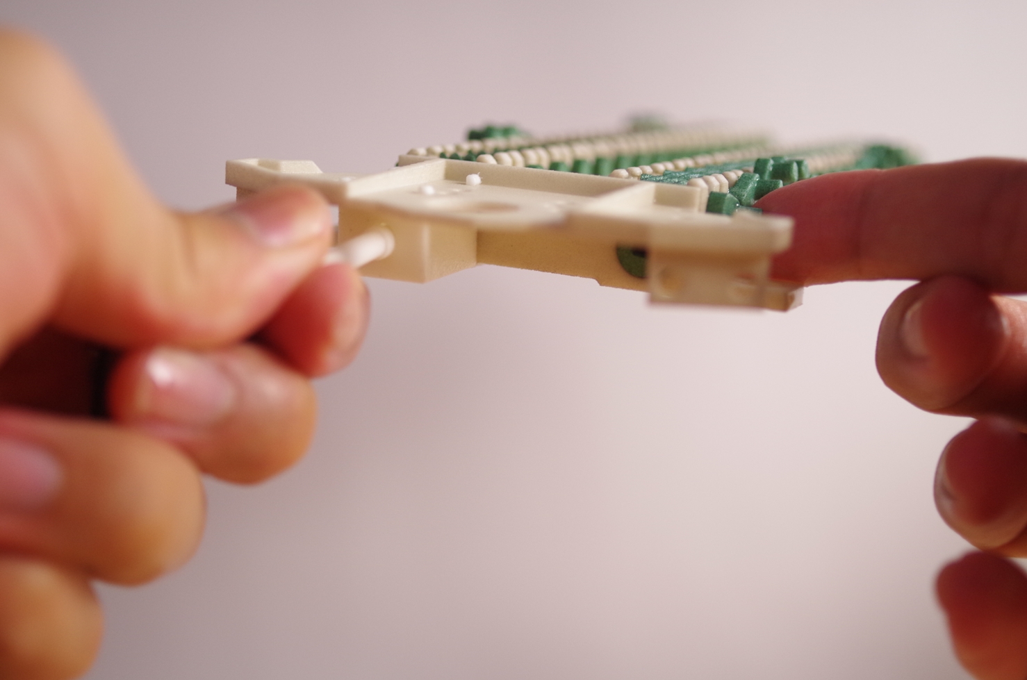
Smoothing using the Tester.
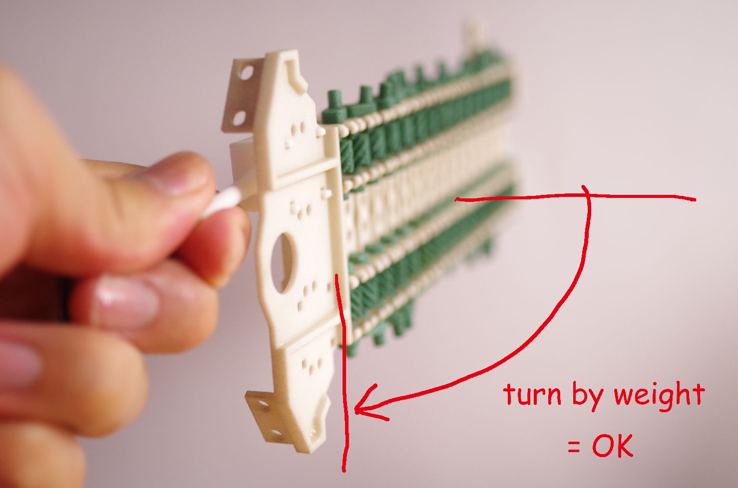
Turn the Shaft manually by using the Tester. First, mount the Tester Base on the Chasis. Through its hole, insert the tip of the Tester into the D-shaped hole of the Shaft. Once you have inserted it successfully, turn the Tester slowly. In the beginning, it does not move easily, but it will gradually get to move with ease. If it is moving with difficulty, move the Tester little by little to the right and left without shifting its place. It will gradually get to move easily. Moreover, if you dampen the whole Tester with water, it would get to move easily. Turn the Tester to the right and to the left a number of times. When it is moving with such ease that you no longer feel that it requires any force, you know that you have succeeded.
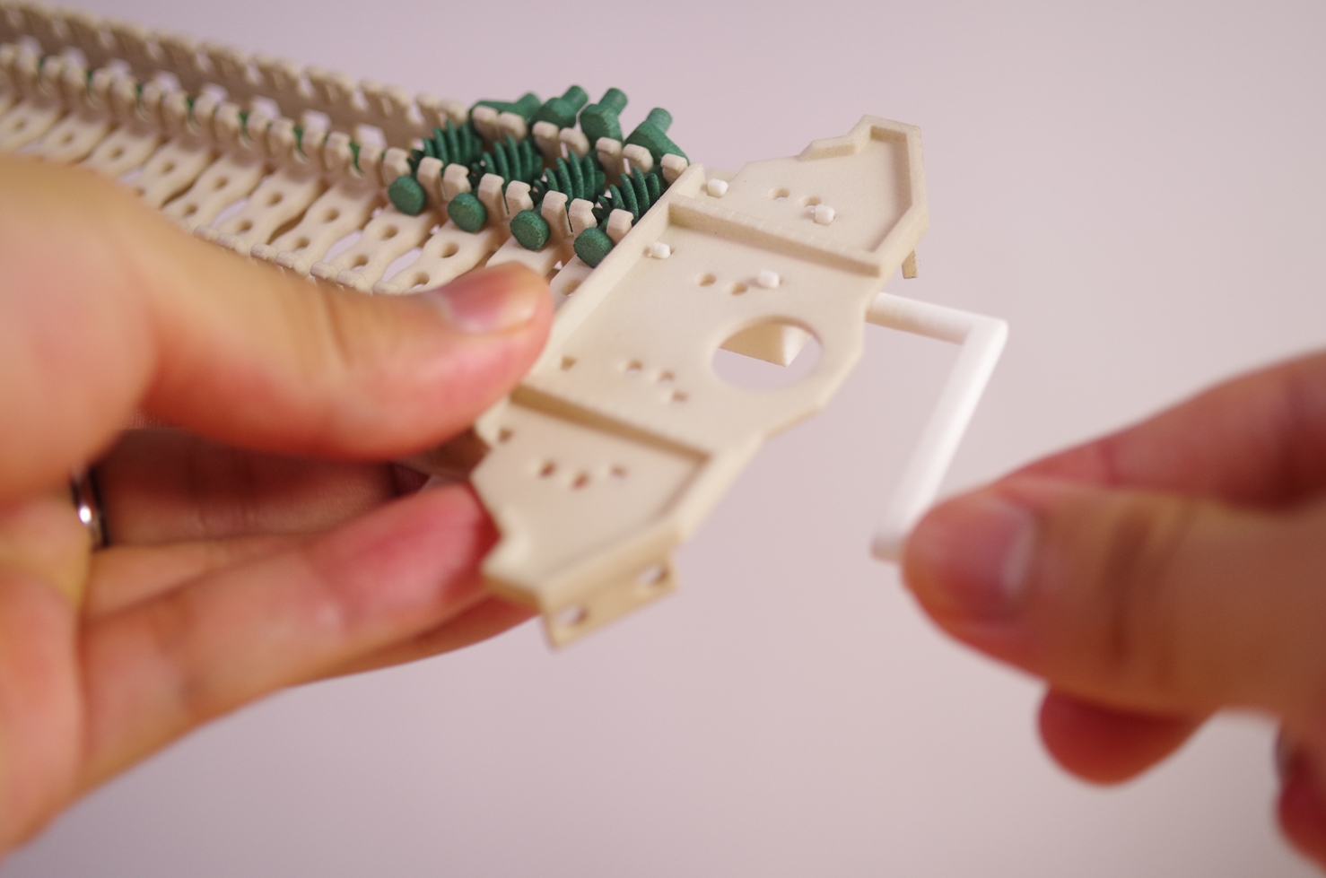
Mount the 16 cranks on one side
Carry out smoothing when you mount the cranks four at a time. Mount all 16 cranks. (See the photograph on top.)
Ultimately, when you hold the Tester, there is the need to feel that the Shaft is rotating as smoothly as by its own weight. (Refer to the picture on the right.)
Once you are done with one side, use the same method to mount the Cranks on the opposite side. (See picture below.)
↓
3.Assemble Legs
The Pre-treatment for the Legs
Depending on the 3D printing, the diameter of the holes of the Legs might be printed smaller than required. Therefore, I recommend that you enlarge the holes when necessary, by using a φ3.5mm drill.

GOOD
BAD
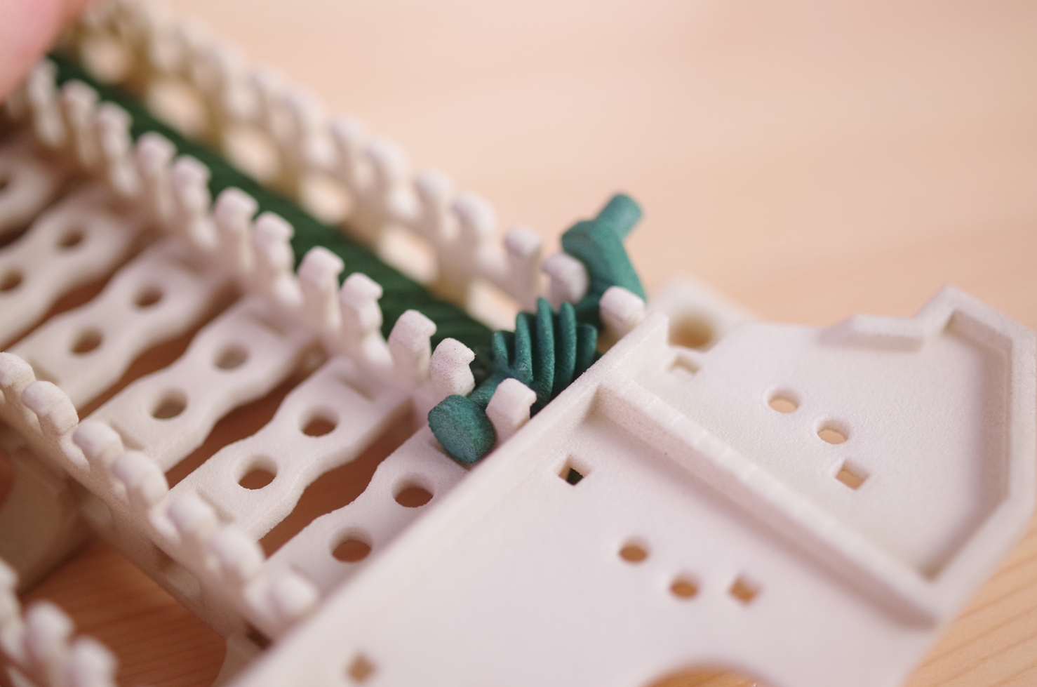
Assemble Legs
First of all, have your pinchers ready. If they are rusty, please be careful that you do not soil the parts with their rust.
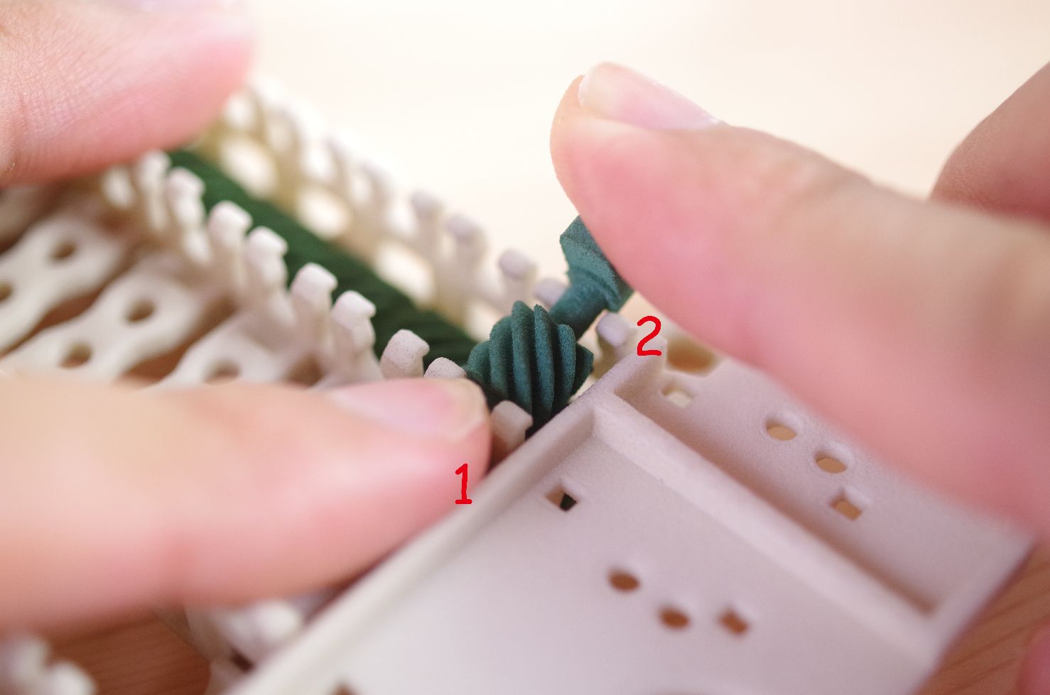
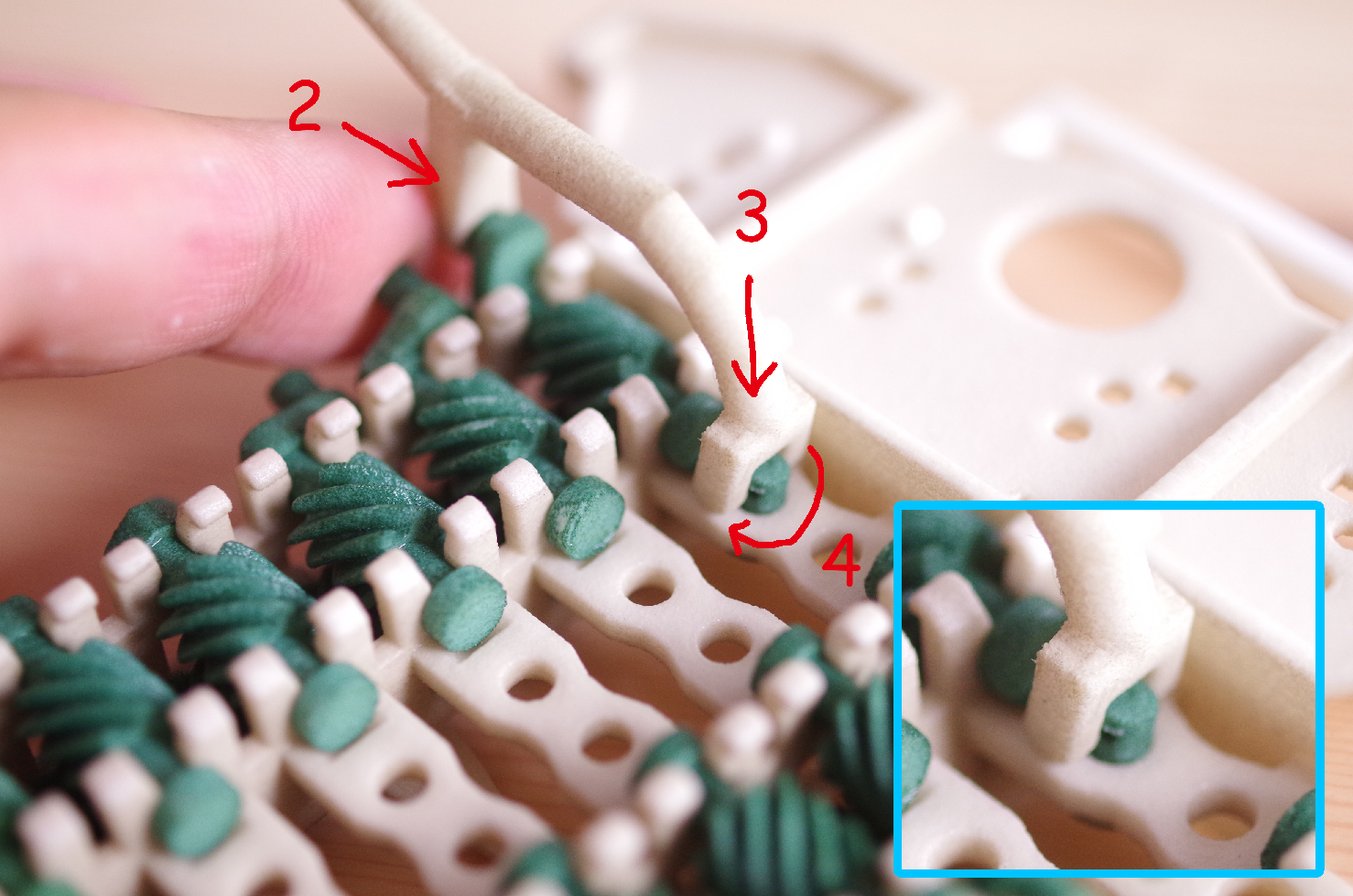
1.Insert the Pin through the Pin hole on the outside of the Chassis.
2.Join together the hole of the Leg and the axis of the Crank.
3.Place the base of the Leg in between the Crank and the Pin.
4.Rotate the Pin to the point where the hole of the Pin can join the projection of the base of the Leg.
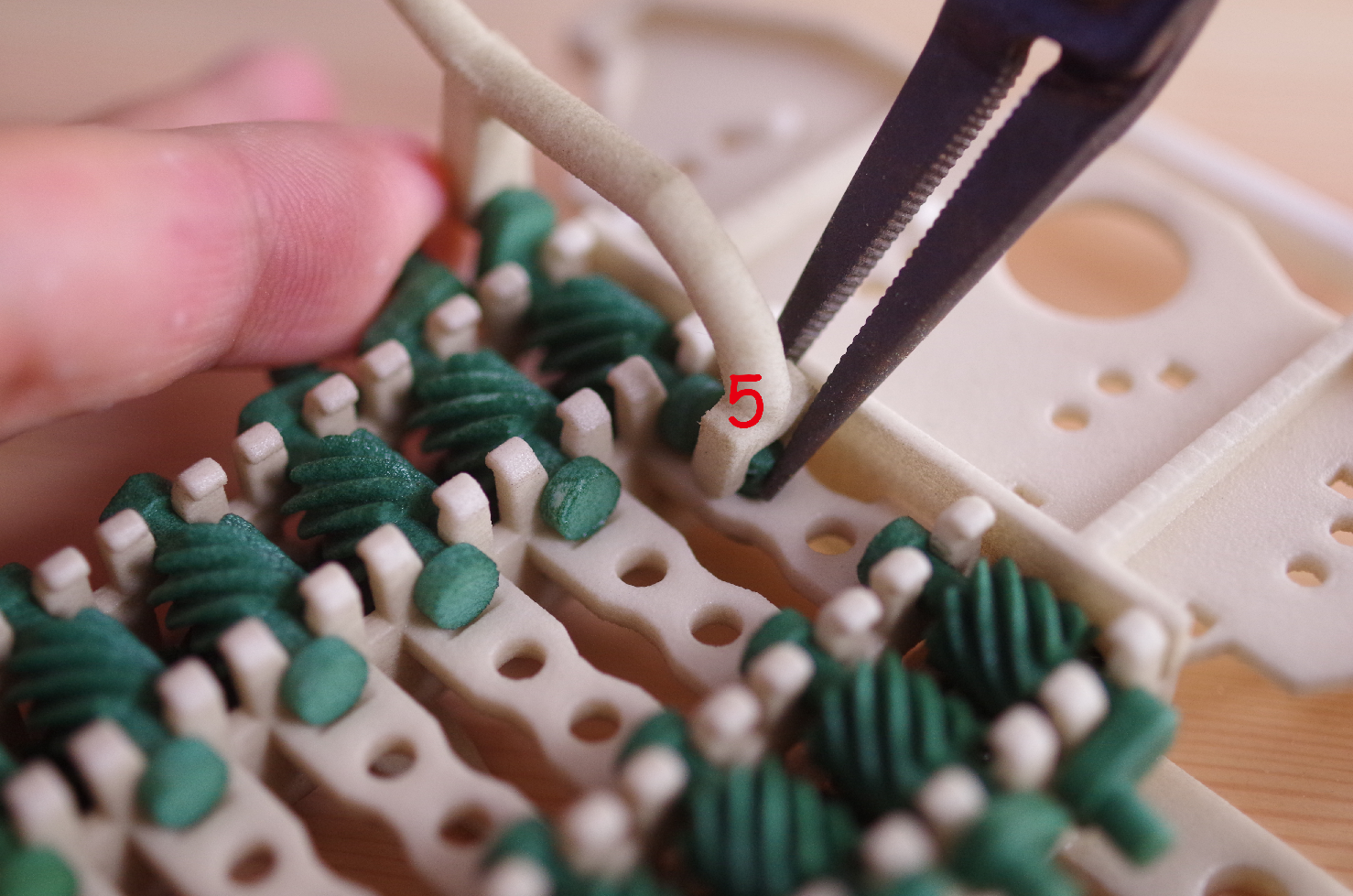
5.Press firmly on the base of the pin and the Leg, using pinchers. This action will enable them to join together.
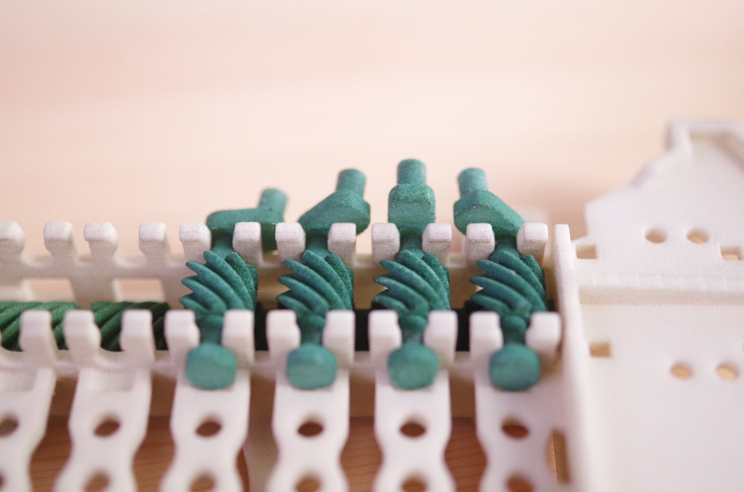
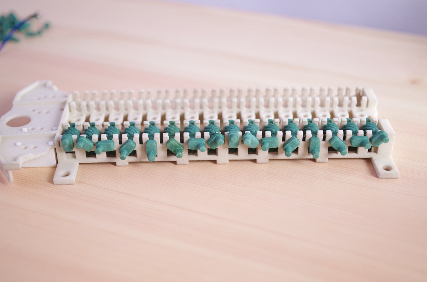
Using this method, mount the four Legs first of all. (See below).
When that has been done, try moving the Tester. If it moves smoothly, there would be no problem.
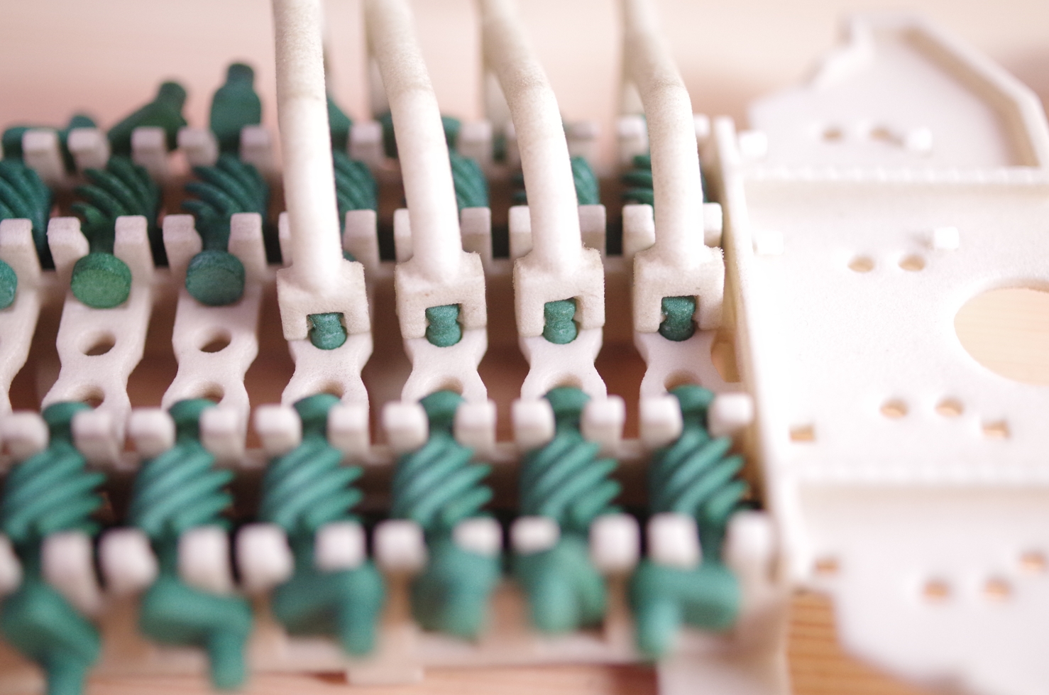
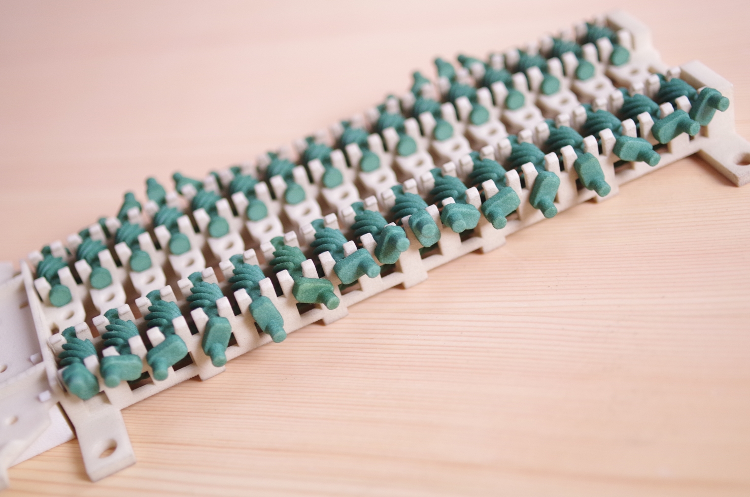
Mounting the remaining Legs
In the same way you have mounted the Cranks, carry out smoothing by the Tester, four Legs at a time. Mount all 32 Legs. When you mount the "Cambria Shell", mount the Legs with the rings at the same locations, referring to the photograph below. Ultimately, please carry out smoothing until all the Legs move smoothly.
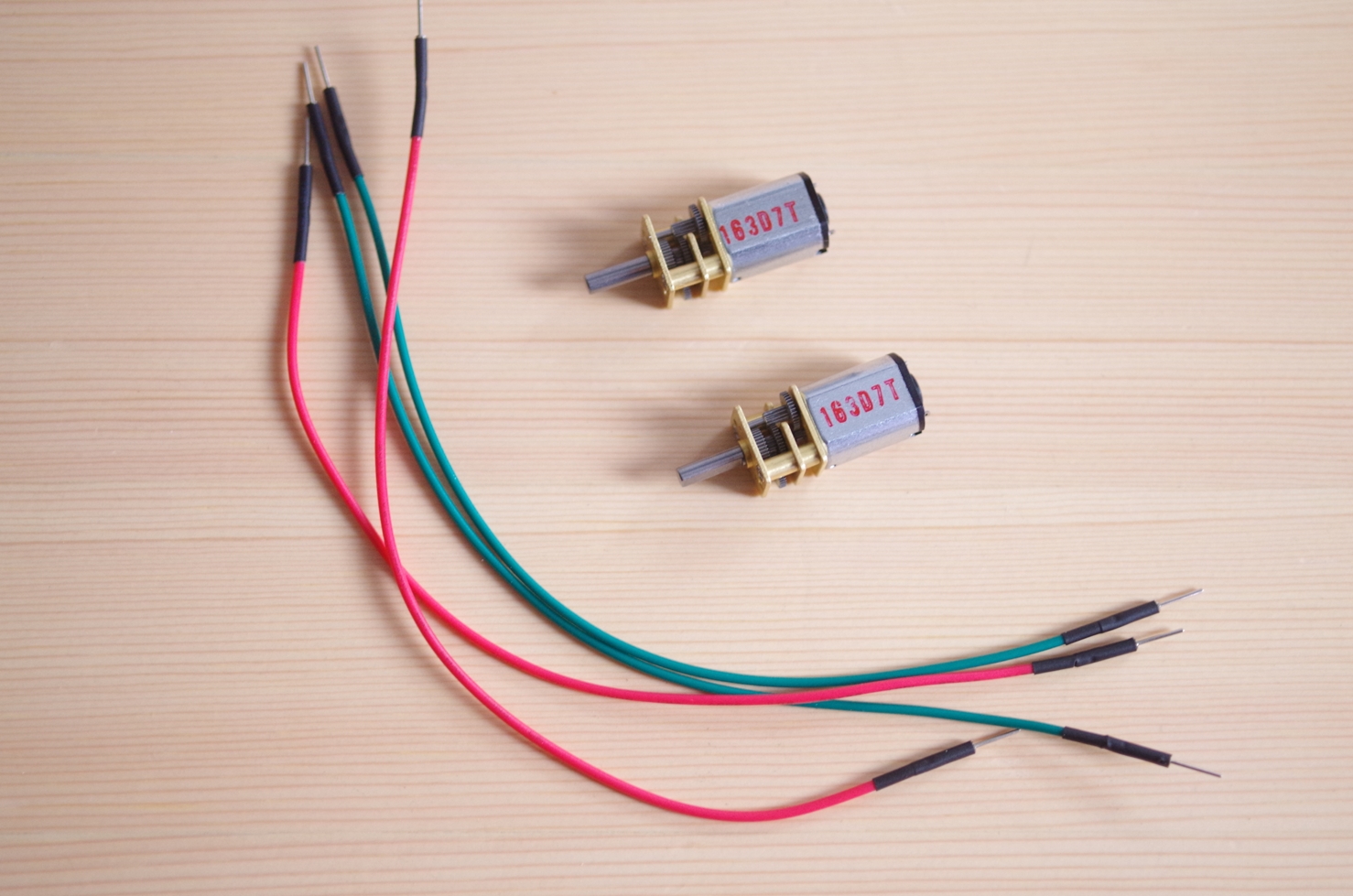
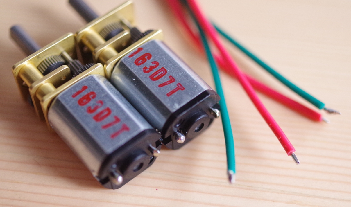
4.Install Gearmotors
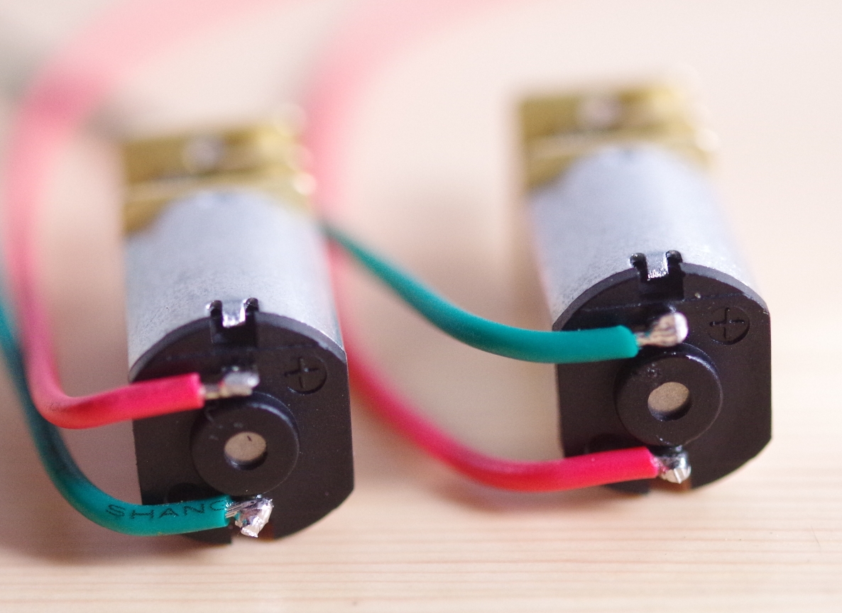
Have ready four jump wires and Gear Motor. Please have ready wires in two different colors.
1. For each jump wire, cut off the tip on one end and remove the coating.
2. Carry out preliminary soldering on the copper wire portions and the motor terminal.
3. Carry out soldering on the jump wires and the motor terminal.
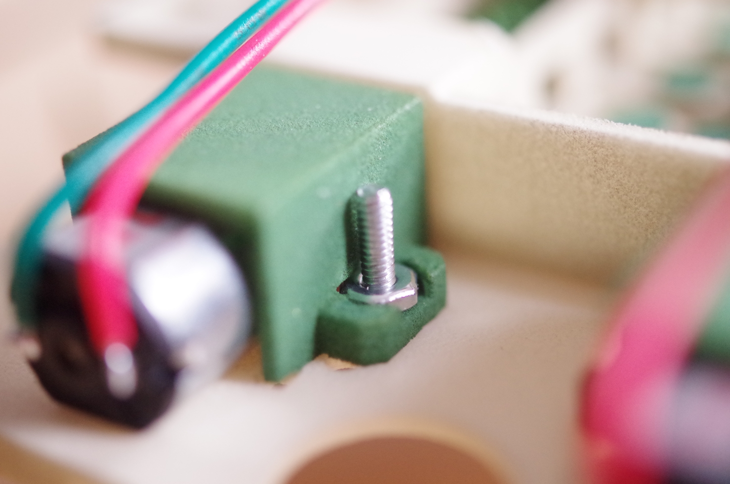
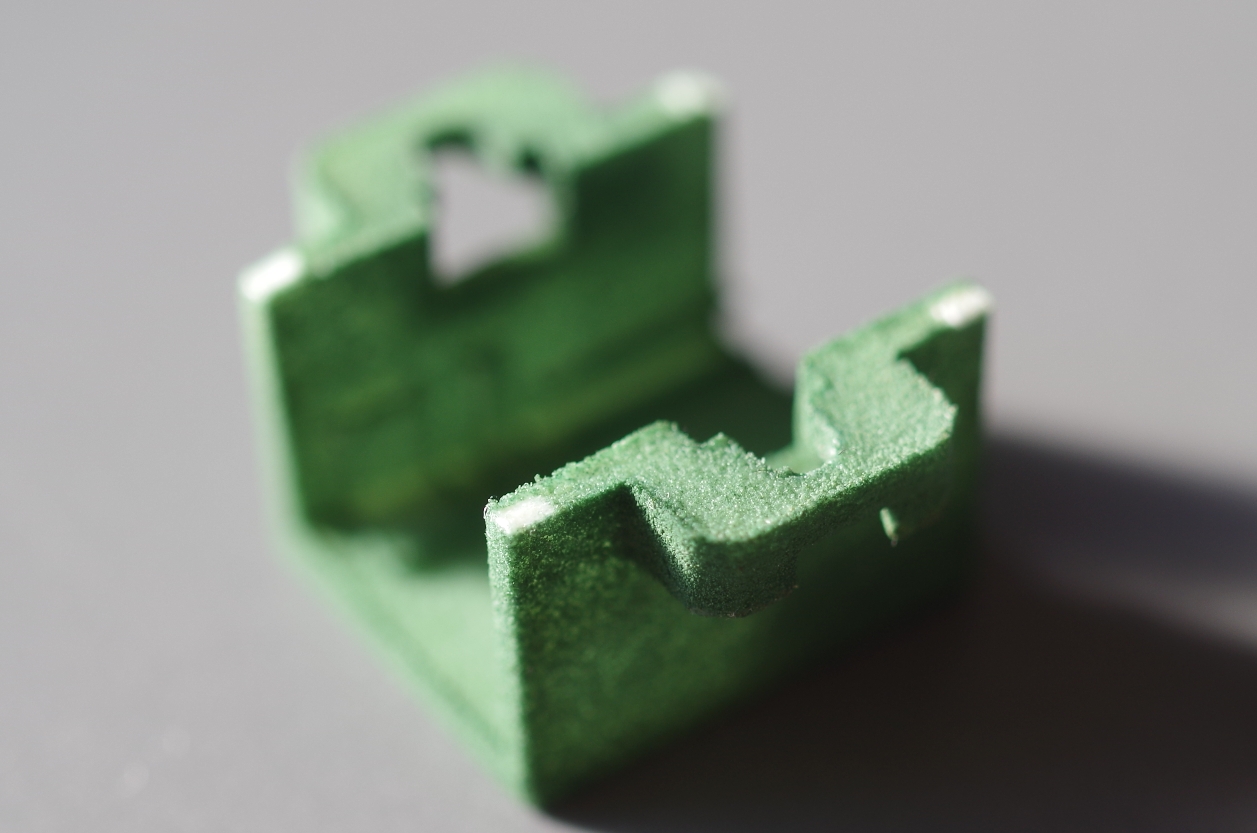
4. Please remove(cut with Nipper) these parts of Motorcover
5. Mount the Gear Motor on the Shaft. As you do so, insert the D-Shaft of the Gear Motor into the D-shaped hole of the Shaft.
6. Mount the Motor Cover on the Gear Motor.
7. Fit the screws and the nuts on the Motor Cover.
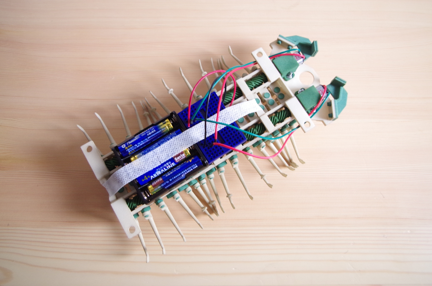
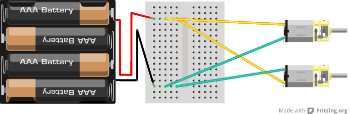
5.Walking test
Simple way to make a circuit.
Referring to the wiring diagram, wire the four batteries and motor on the Bread Board and carry out a running test. Please stabilize the Bread Board and the batteries, using a tape, so that the circuit does not fall down during running.
The switching ON / OFF during running is done with the taking out and putting in of the batteries.
You have succeeded if it moves straight ahead when the power is on.
If you get any problem and question, please mail me .