


Process
Required times:
Printing: about 3hours (by Replicator2)
Assembling: about 1~2hour
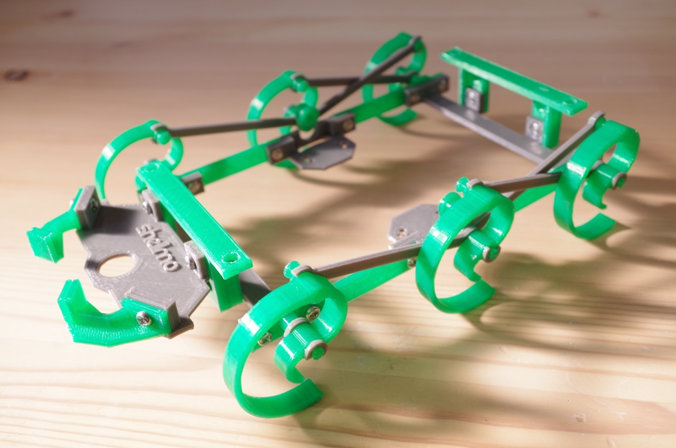
RepWalker Shellmo from shodelta on Sketchfab.
2.Making parts
3D printing datail:
Printer:Replicator2
Material:PLA
Infill:10%
Number of Shells:2 (only Crank: 3)
LayerHeight:0.30mm
Hotend Temperature:250℃
Extruding Speed:90mm/s
Raft:Yes
Support:Only for Crank,MotorCover,Claw
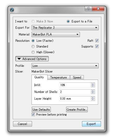
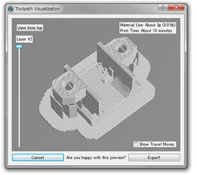
Printing with MakerWare™
Other Parts
1.Parts and Tools
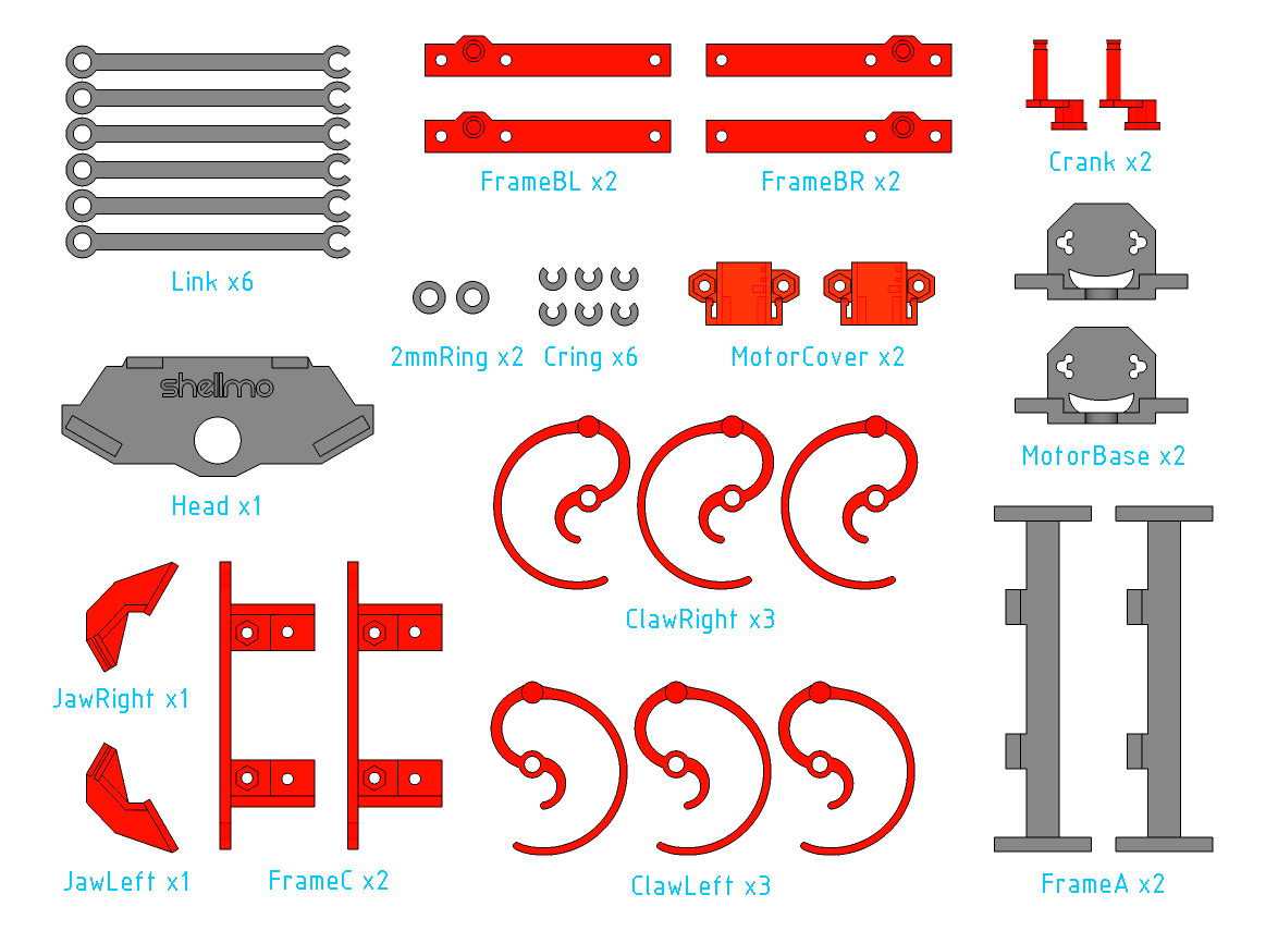
3D printed parts:
Download All: .Stl Download page
RW_Head *1
RW_JawLeft *1
RW_JawRight *1
RW_ClawLeft *3
RW_ClawRight *3
RW_FrameA *2
RW_FrameBL *2
RW_FrameBR *2
RW_FrameC *2
RW_MotorBase *2
RW_Link *6
RW_Cring *6
RW_2mmRing *2
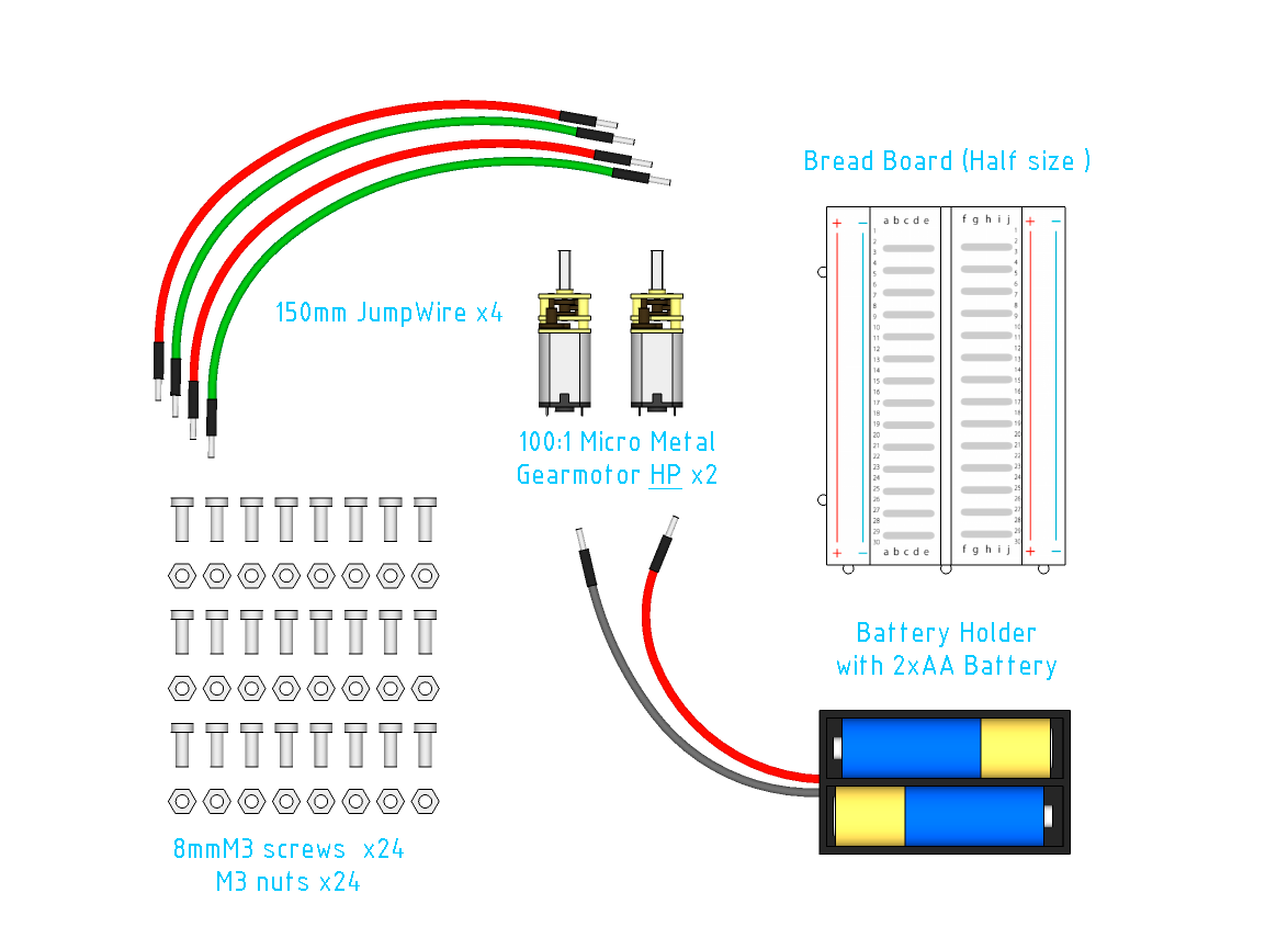
Other parts:
100:1 Micro Metal Gearmotor "HP" *2 Pololu RobotShop
Jumpwires *4 Sparkfun
Breadboard *1 Sparkfun
AABattery *2 Sparkfun
2xAABatteryHolder *1 Sparkfun
8mmLength M3Screws: Pololu
M3Nuts: Pololu
Tools:
Pliers
Solder iron and Solder
Drill and Drillbit(φ3.0mm)
Screwdriver(+ shape)
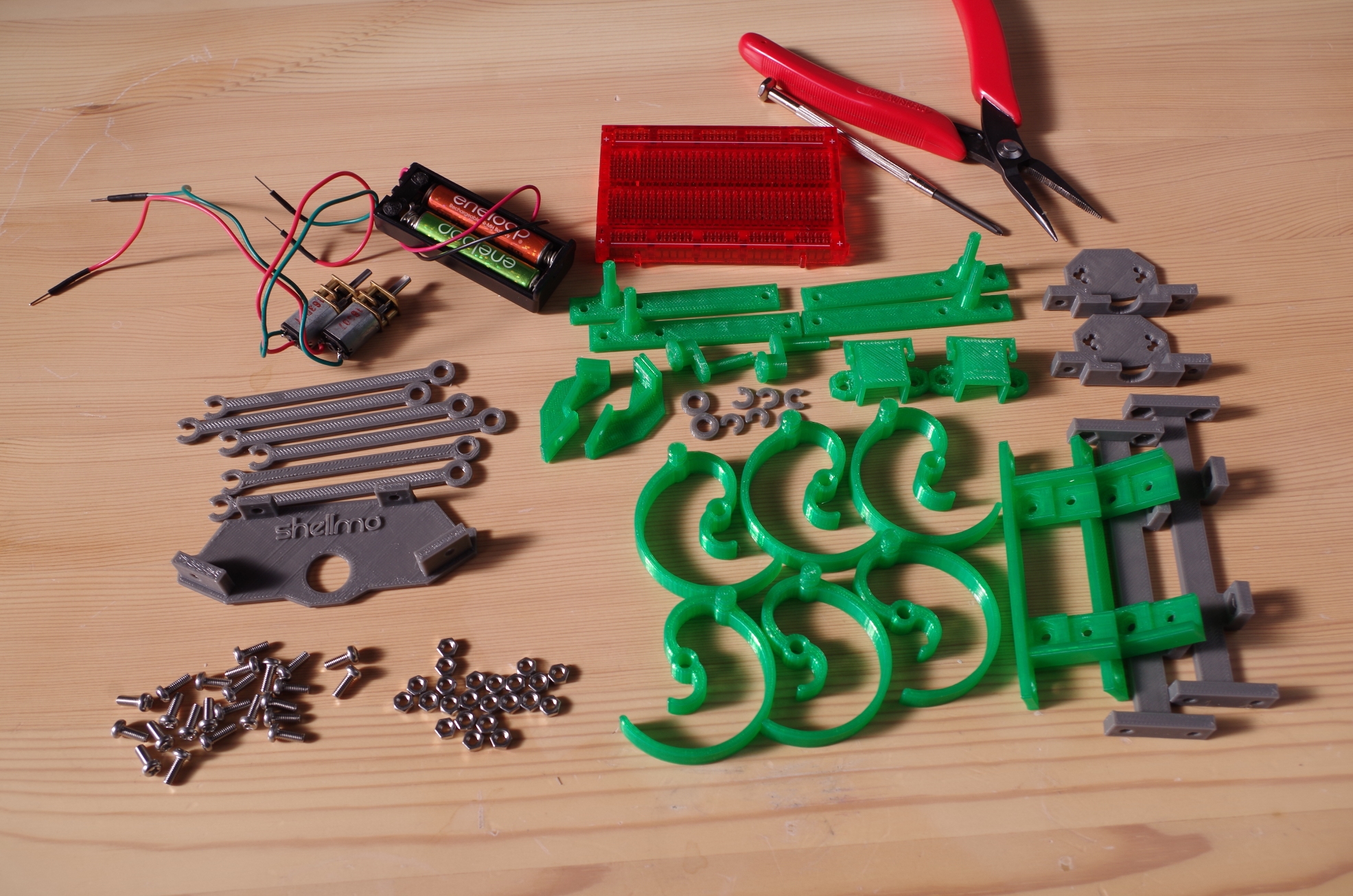
3D printed parts
Parts and Tools
Printing detail of each parts:
Head
JawLeft, JawRight
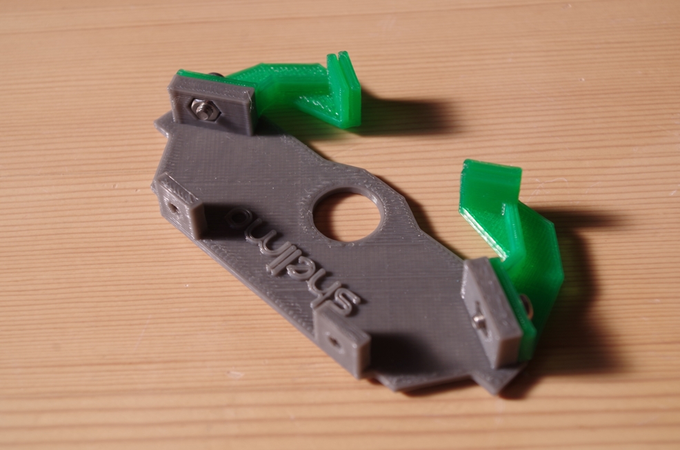
FrameA
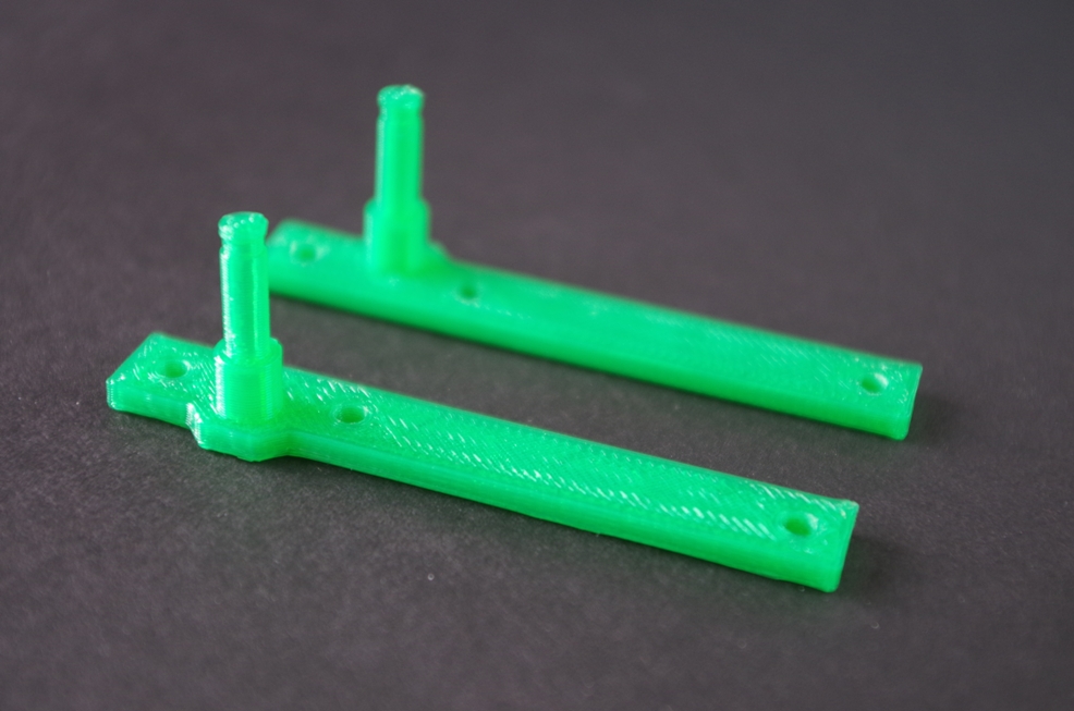
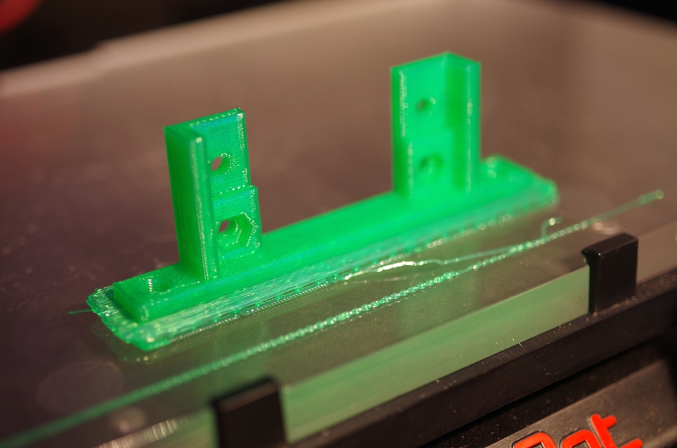
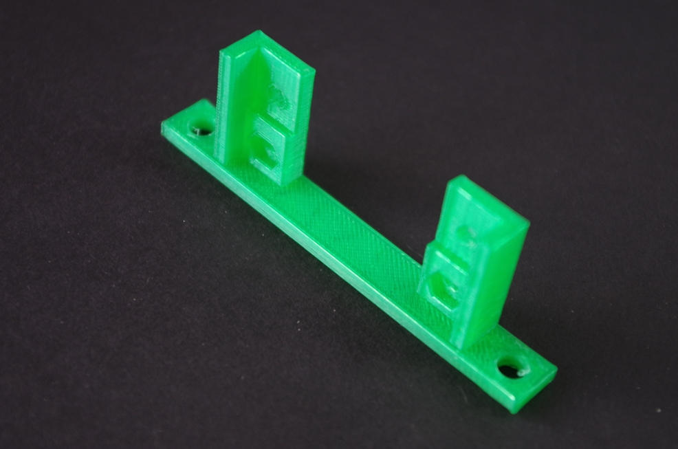
FrameBL,FrameBR
FrameC
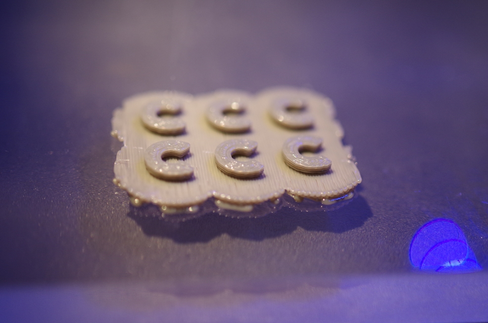
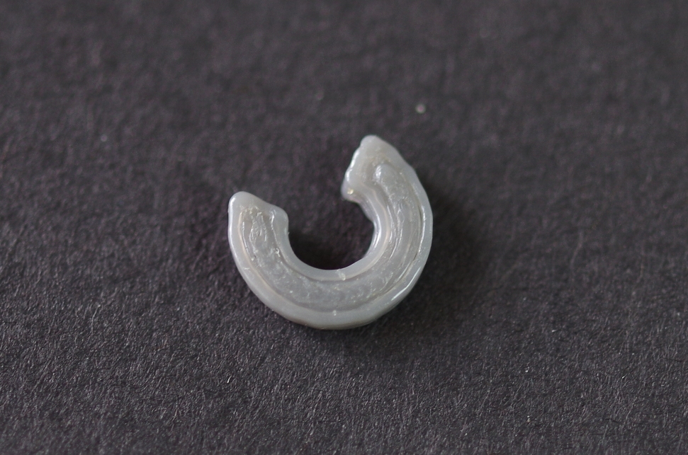
Claw
Support: Yes
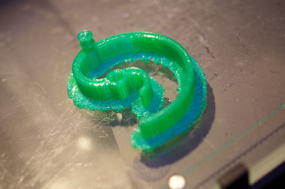
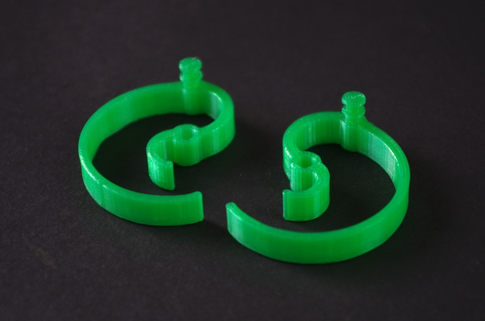
Cring
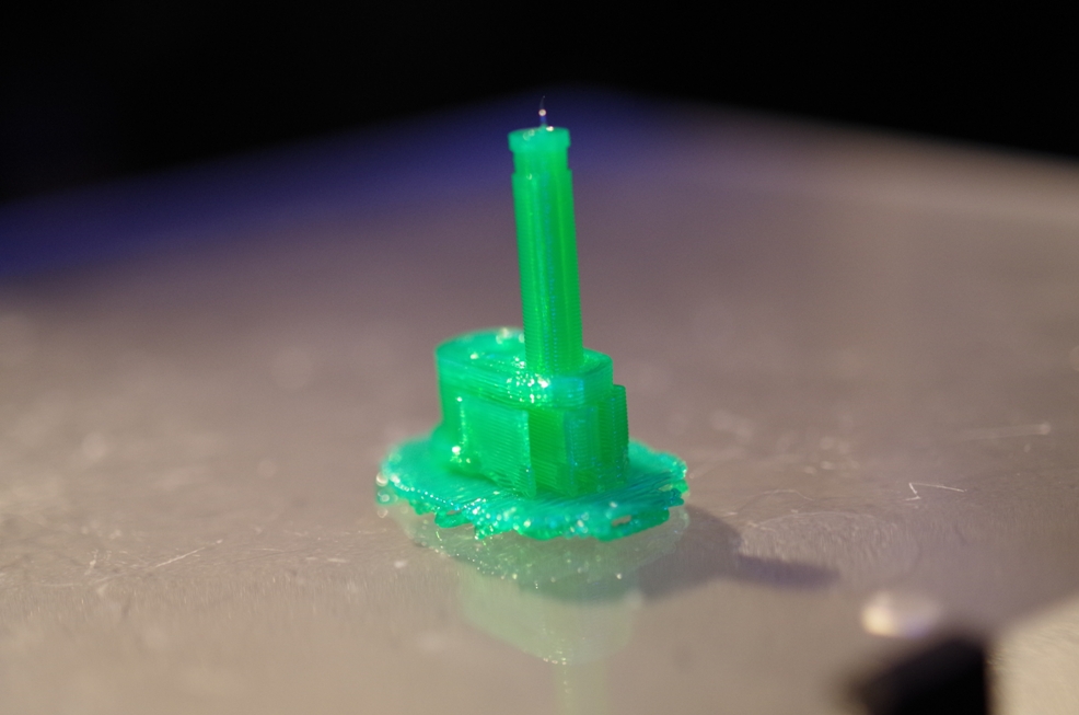
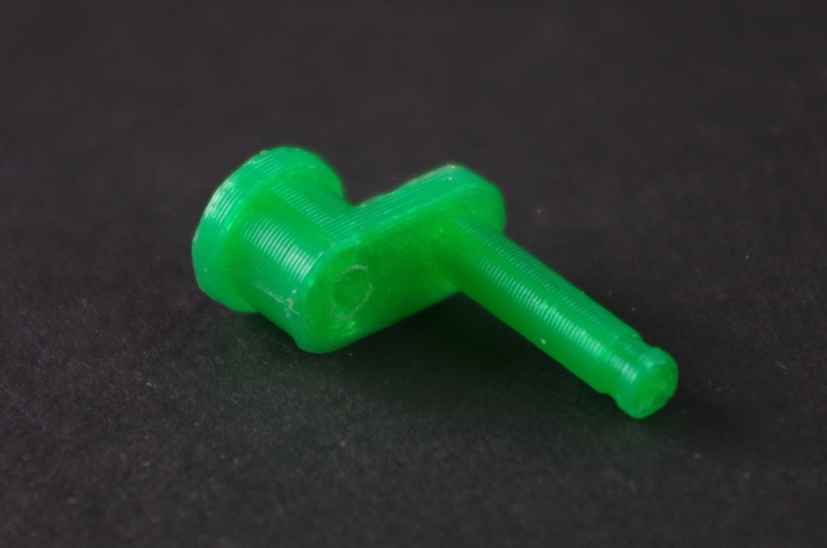
Crank
Support: Yes
Number of Shell: 3
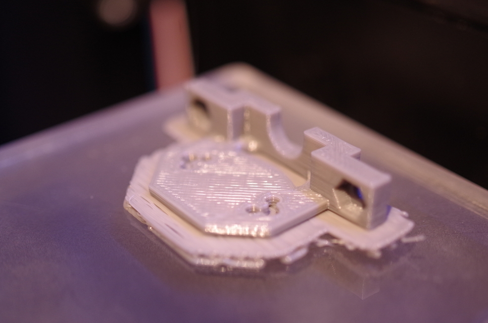
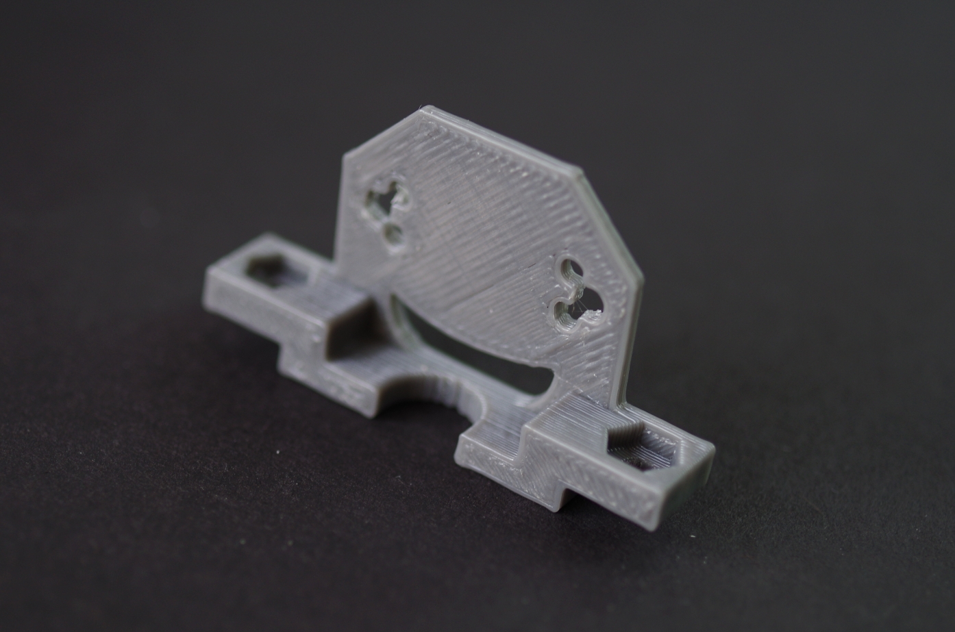
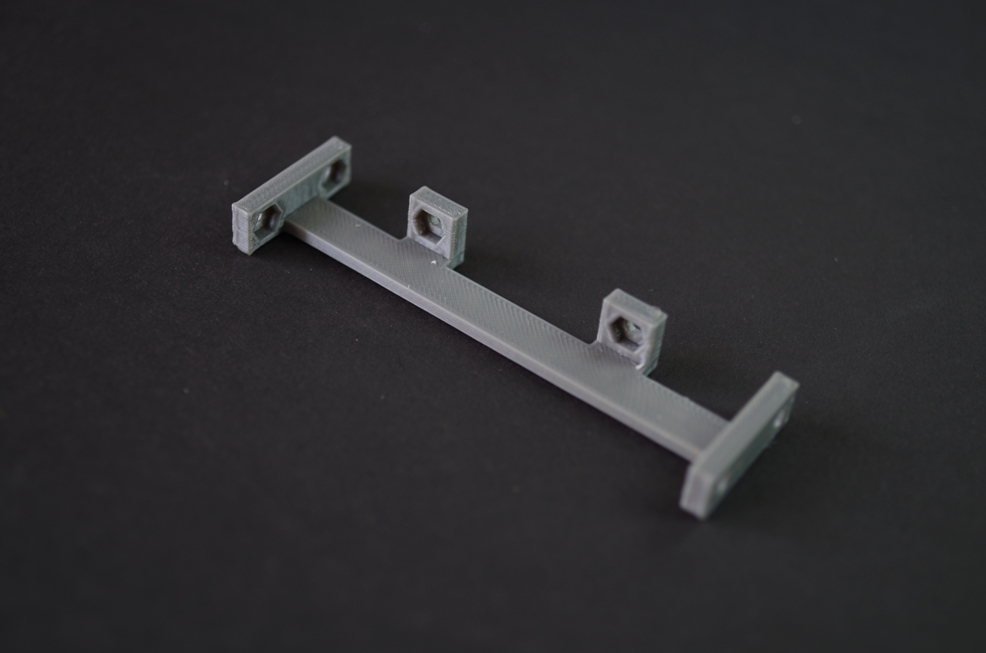
Motorbase
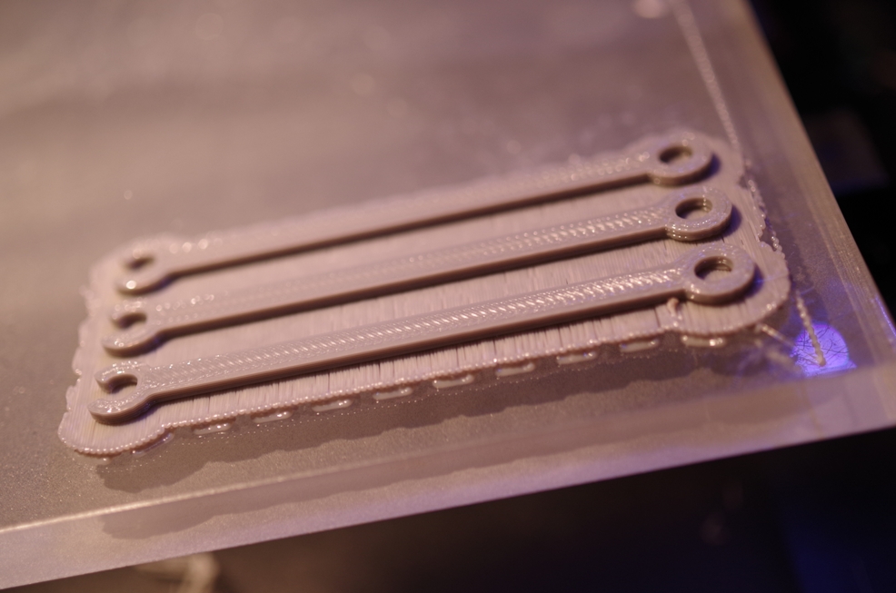
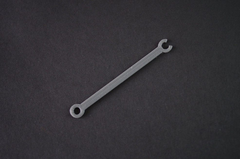
Link
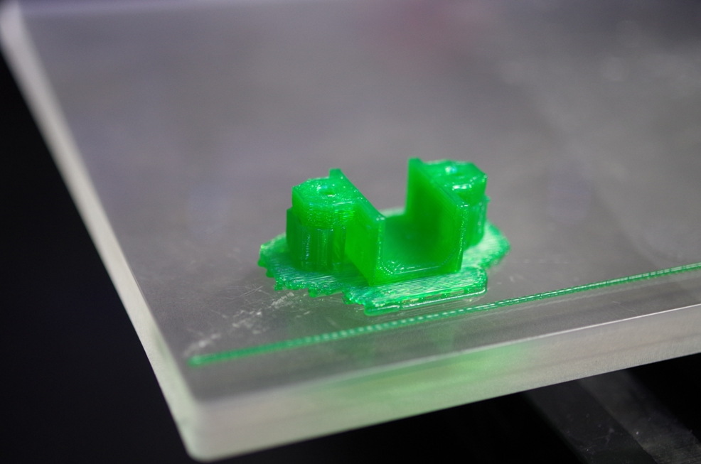
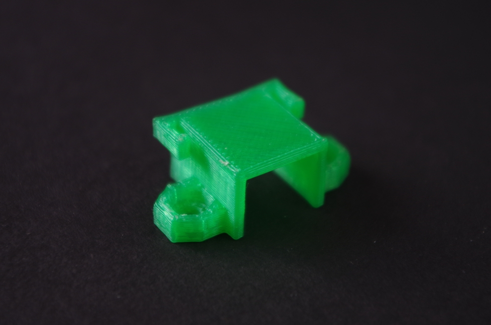
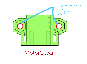
MotorCover
Support: Yes
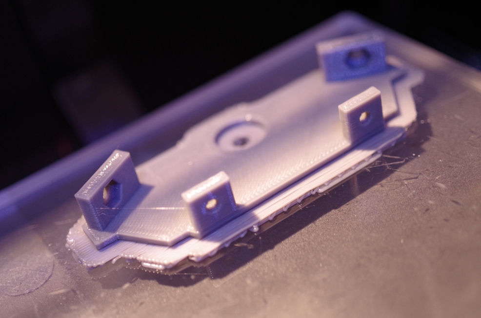
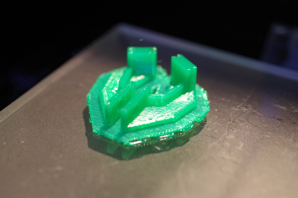
Just after printing
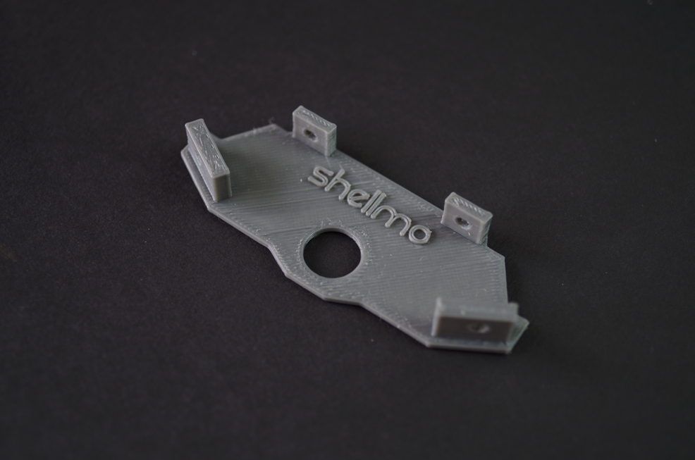
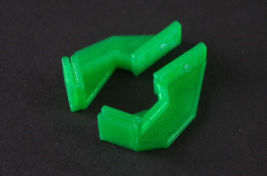
After removing the raft and burrs
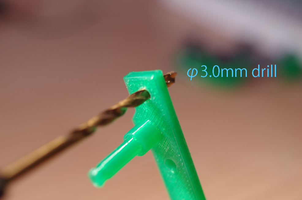
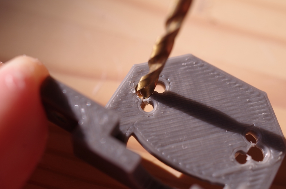
Drilling 3mm Hole for M3 Screw
Basically, I designed every screw hole diameter as 3.2mm so, if you can insert M3 screw to the hole, you don't have to do this process. But, if the hole is small, please use 3.0mm drill for expansion.
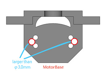
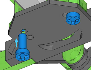
The screw hole on "Motorbase" is a little special.
Basically, please use the center hole (the red circles on the picture) for M3 screw.
Please don't forget to drill the hole of MotorCover, too↓
Points of using screws and nuts (24 points)
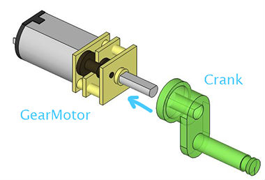
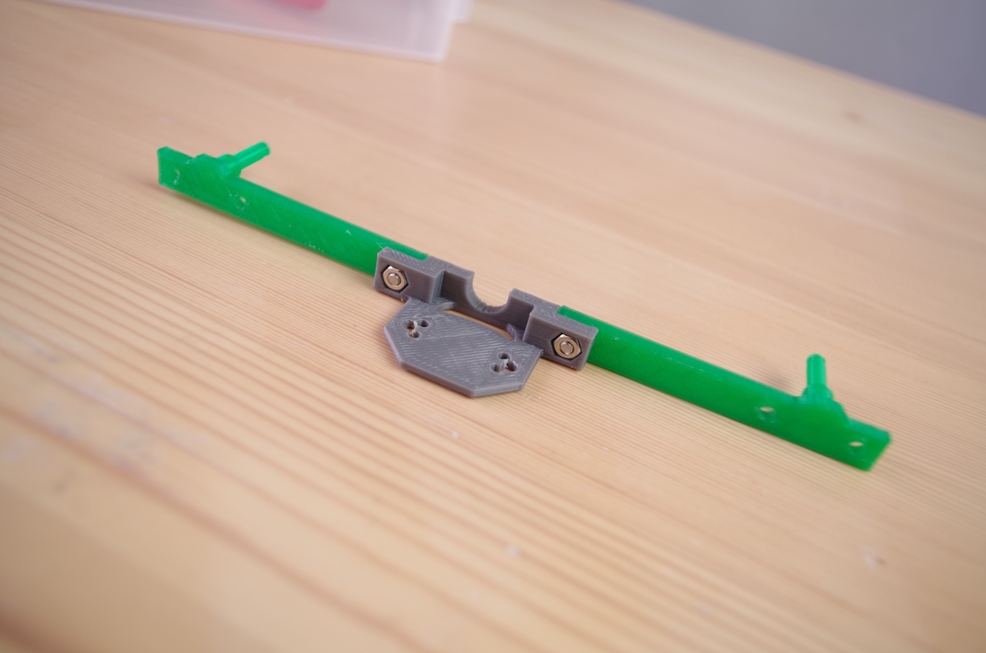
Insert test of Crank
Before assembling, please check the size of hole of "Crank". Please try to insert Gearmotor to Crank like the right picture.
- If the crank drop when you peel off below, it's loose.
- If you want to use hammer to insert,
it's tight. (if you feel tight, stop insert)
Basically, I recommend to use φ3.45mm Crank. But, if it's loose or tight, please change Crank.
φ3.65mm Crank (more loose)
φ3.45mm Crank (Normal)
φ3.36mm Crank (more tight)
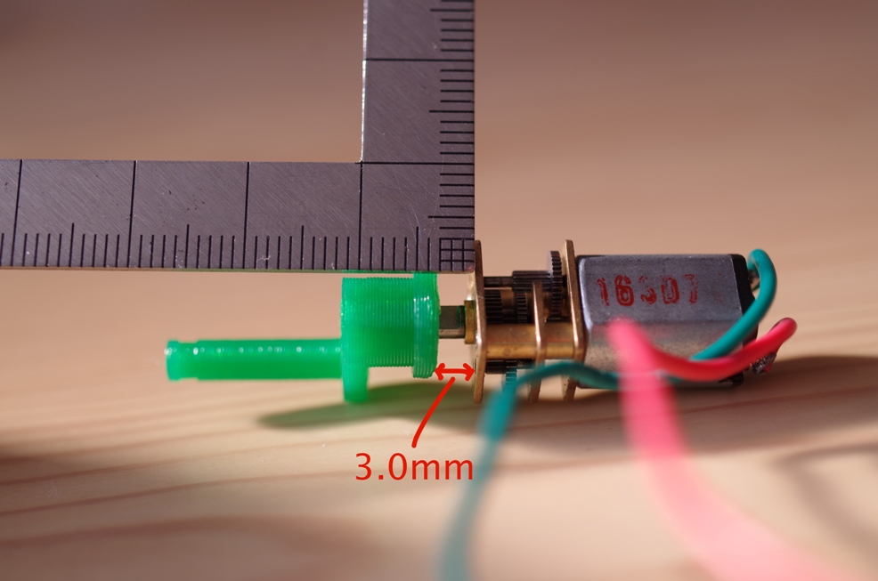
After insert test, please leave off Gearmotor from Crank now
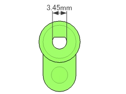
φ3.45mm Crank
Insert test
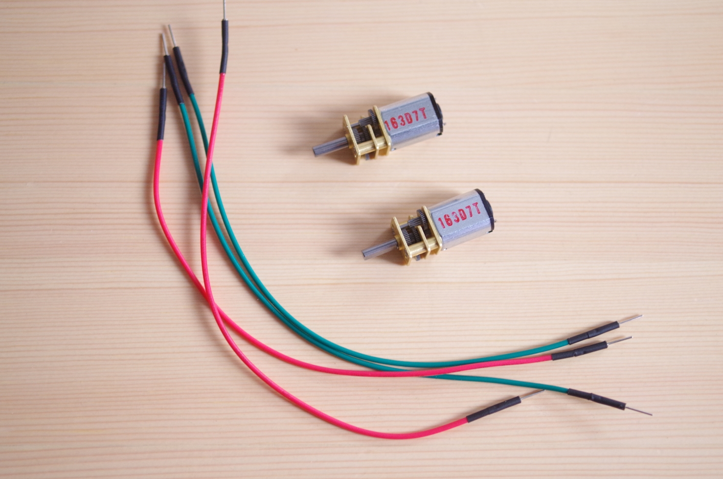
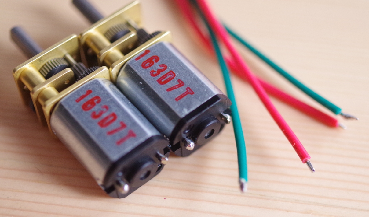
3.Solder Gearmotors
Have ready four jump wires and Gear Motor. Please have ready wires in two different colors.
1. For each jump wire, cut off the tip on one end and remove the coating.
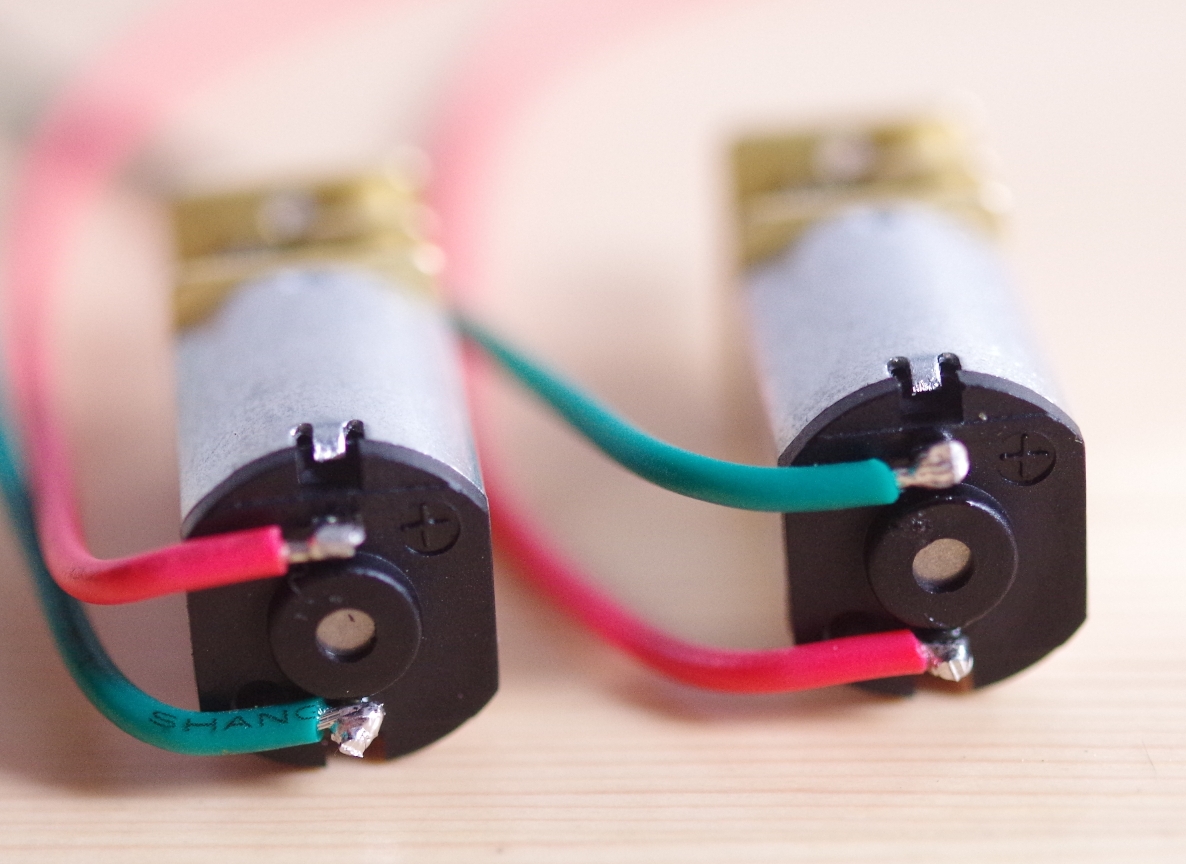
2. Carry out preliminary soldering on the copper wire portions and the motor terminal.
3. Carry out soldering on the jump wires and the motor terminal.
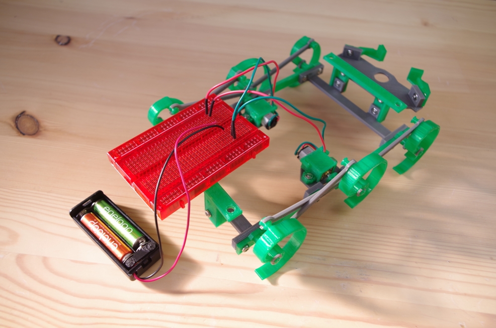
5.Walking test
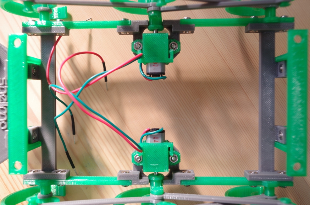
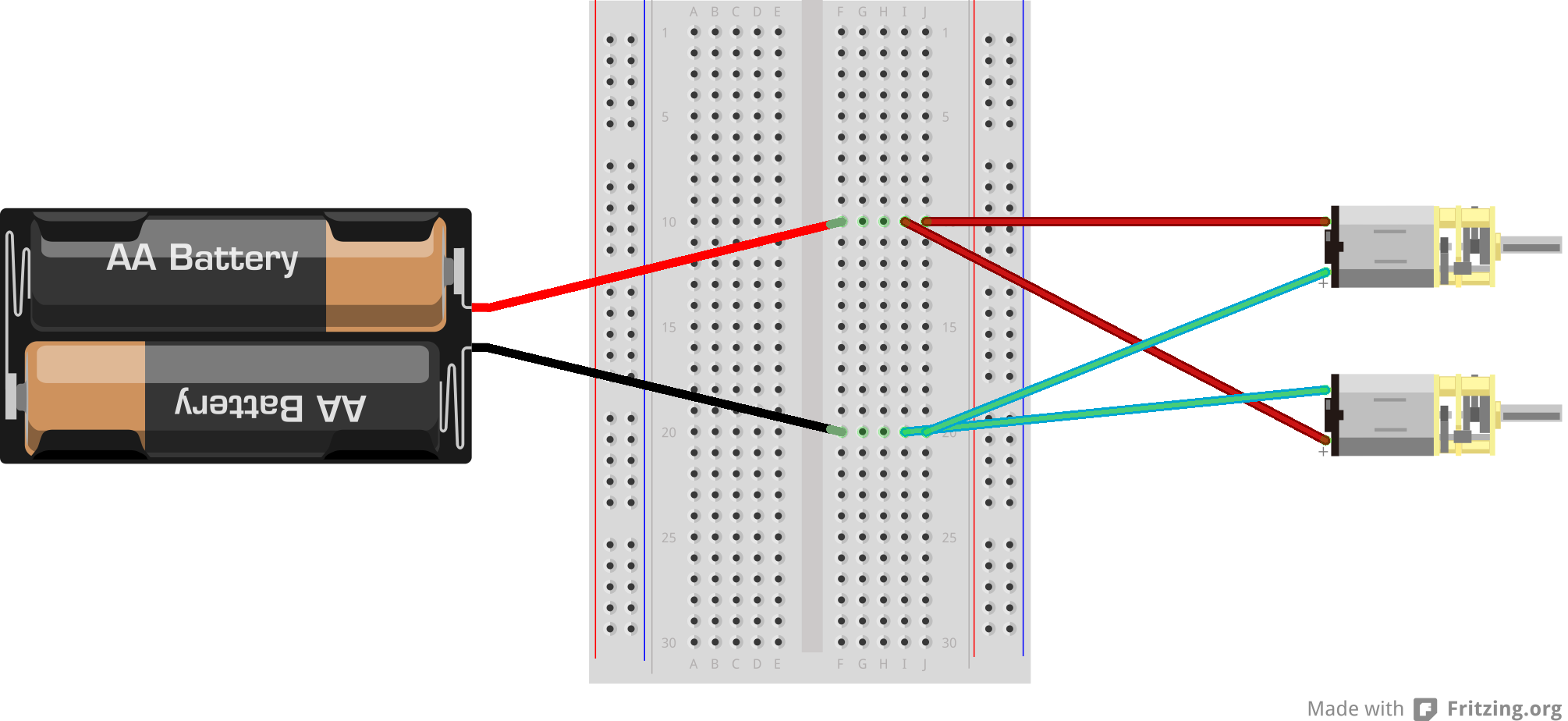
Simple way to make a circuit.
Referring to the wiring diagram, wire the four batteries and motor on the Bread Board and carry out a running test. Please stabilize the Bread Board and the batteries, using a tape, so that the circuit does not fall down during running.
The switching ON / OFF during running is done with the taking out and putting in of the batteries.
You have succeeded if it moves straight ahead when the power is on.
4.Assemble
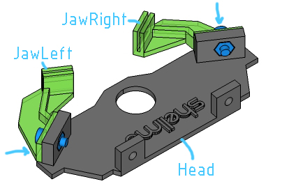
1.Install Jaw to Head
- JawRight
- JawLeft
- Head
- Screw&Nut *2
Install JawLeft and JawRight to Head.
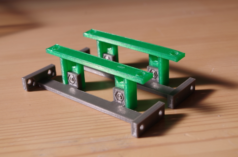
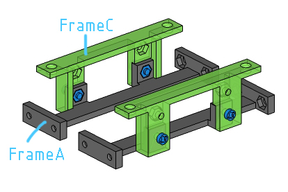
2.Attach FrameA to FrameC
- FrameA *2
- FrameC *2
- Screw&Nut *4
Attach FrameA to FrameC.
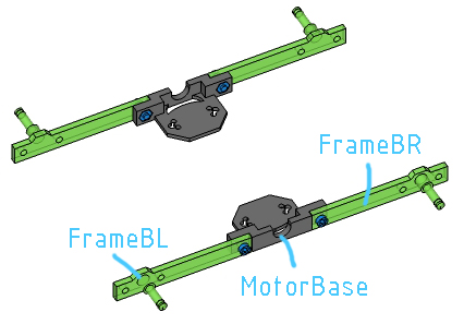
3.Attach FrameB to MotorBase
- FrameBL *2
- FrameBR *2
- MotorBase *2
- Screw&Nut *4
Attach FrameB to MotorBase.
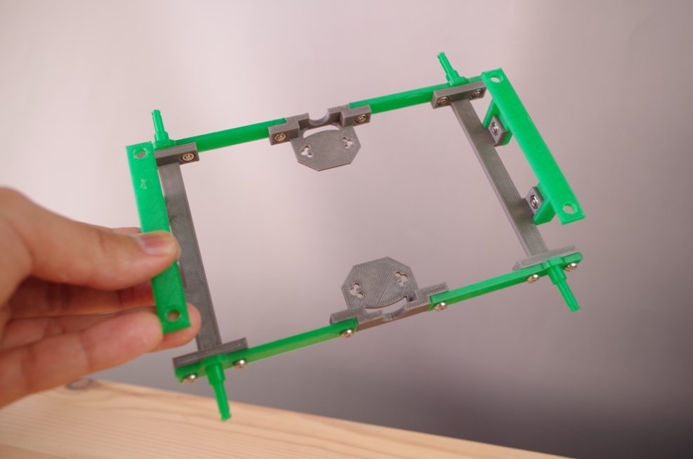
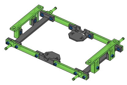
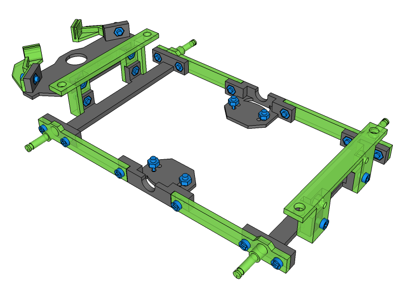
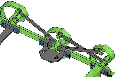
4.Combine Frames
- Screw&Nut *8
Combine all frames as one frame.
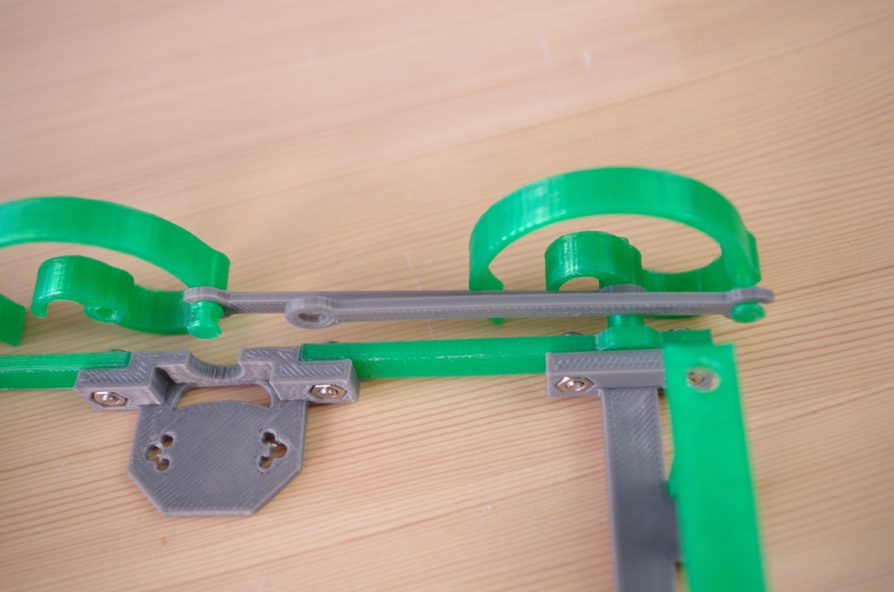
5.Attach Link to ClawRight
- ClawRight *3
- Link *3
Attach Link to ClawRight. You can attach link to Claw like the picture.
Becareful about the place to attach.There are 2 places (inside and outside) to attach. Please attach 2 links to inside and 1 link to outside.
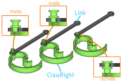
inside and outsie
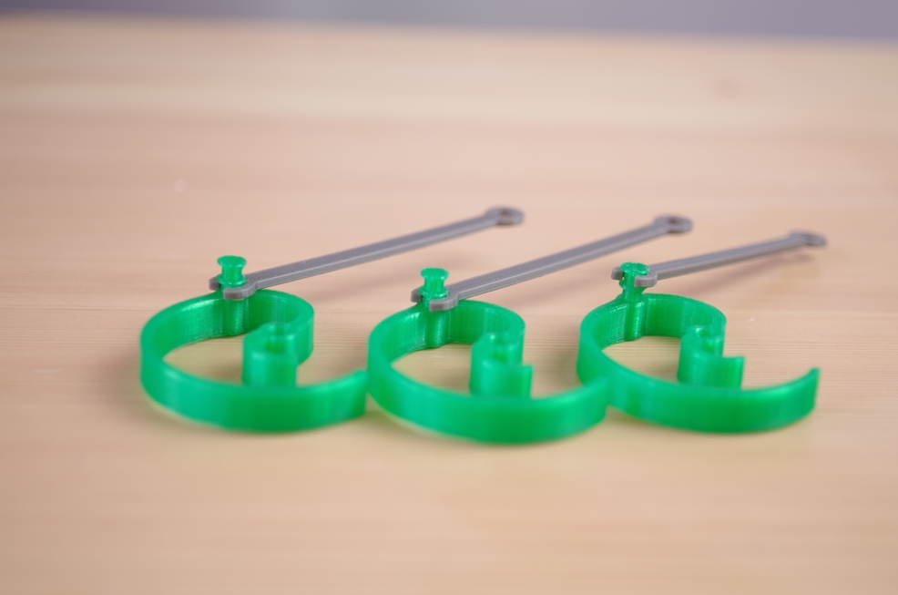
Please attach 2 links to inside and 1link to outside
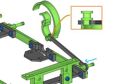
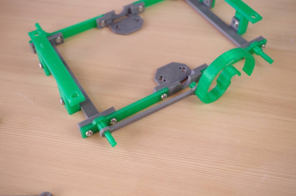
6.Attach Link with ClawRight(inside) to FrameBL
- ClawRight(inside) *1
Attach other tip of link of ClawRight(inside) to FrameBL.
7.Attach ClawRight(outside) to FrameBL
- ClawRight(outside) *1
Attach ClawRight(outside) to FrameBL
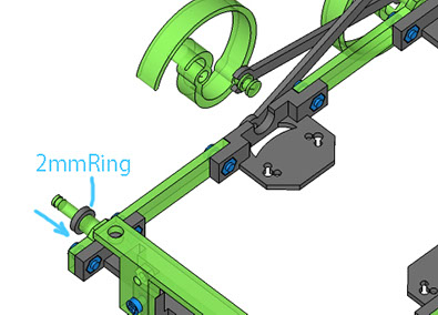
8.Attach 2mmRing to FrameBR
- 2mmRing *1
Attach 2mmRing to FrameBR
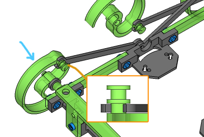
9.Attach ClawRight(inside) to FrameBR
- ClawRight(inside) *1
Attach ClawRight(inside) to FrameBR
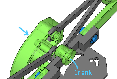
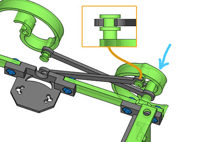
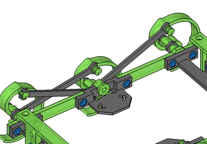
10.Attach ClawRight(inside) and links to Crank
- ClawRight(inside) *1
- Crank *1
Attach the links and claw to crank like these pictures. Becaful the sequence.
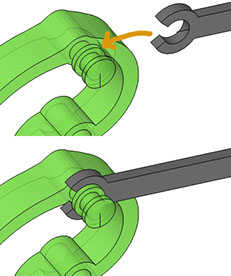
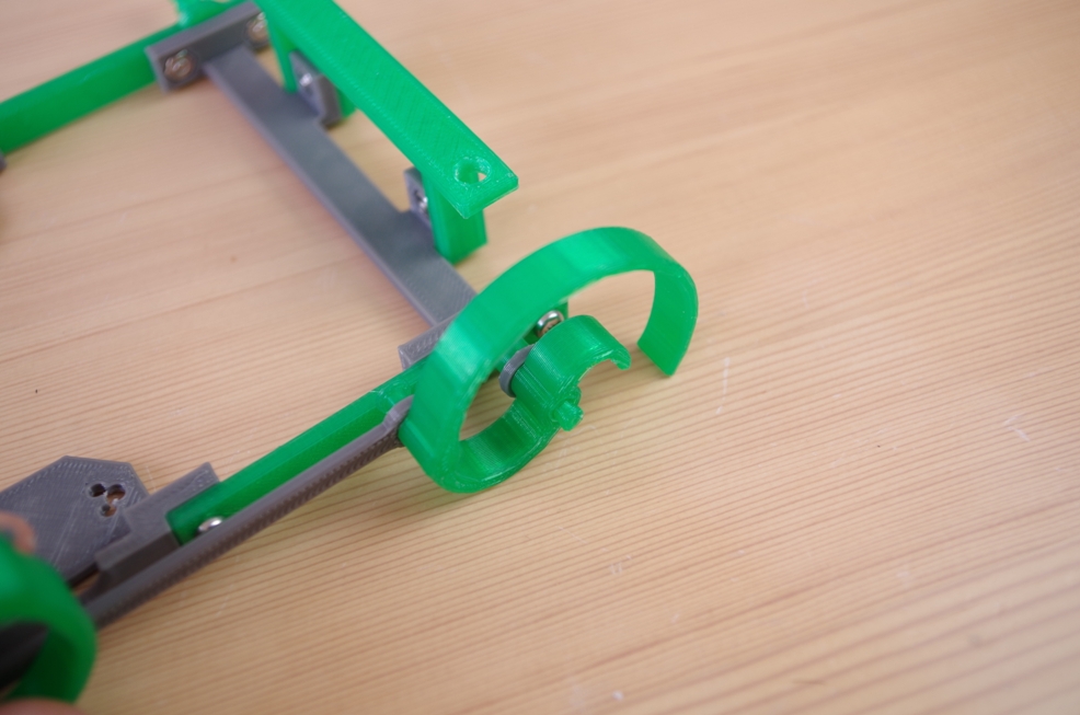
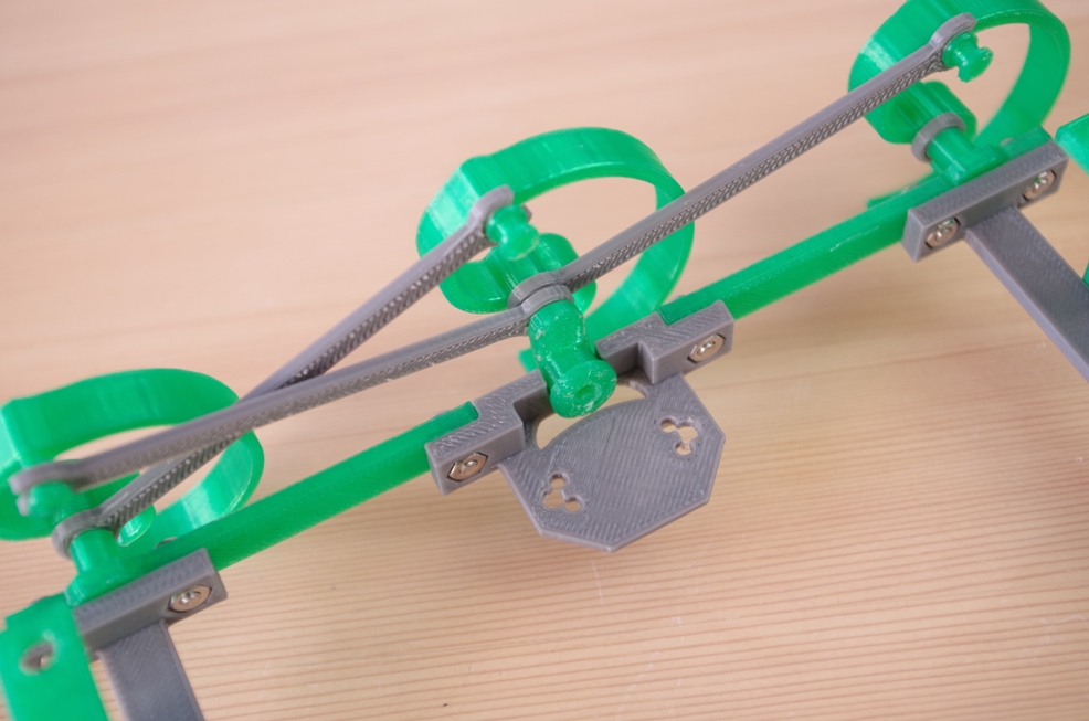
11.Attach Crings to Crank, FrameBL and FrameBR
- Cring *3
Attach Crings to each claws. You will need plier to attach Crings. Please attach like the right picture.
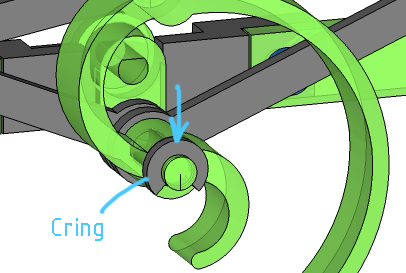
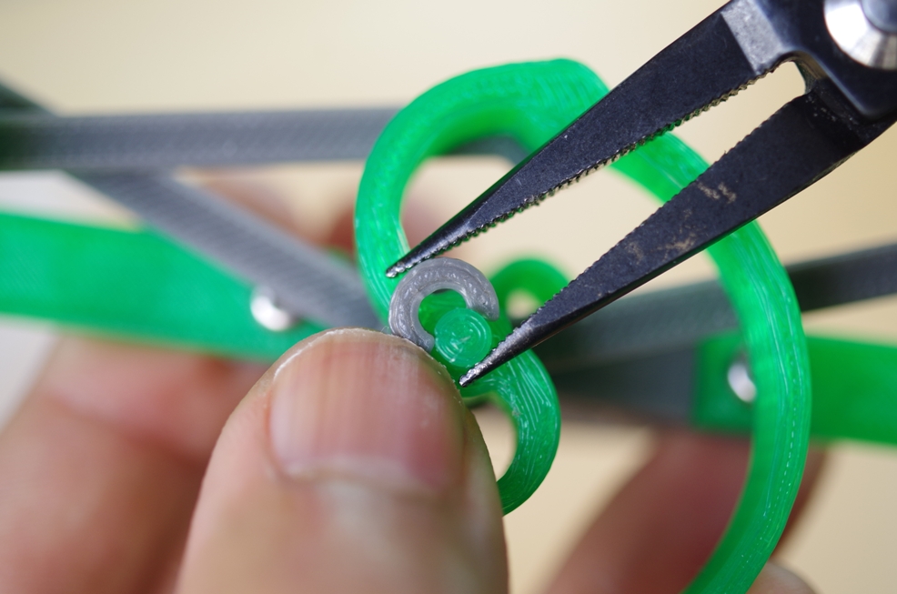
You can use pliers for attaching Cring
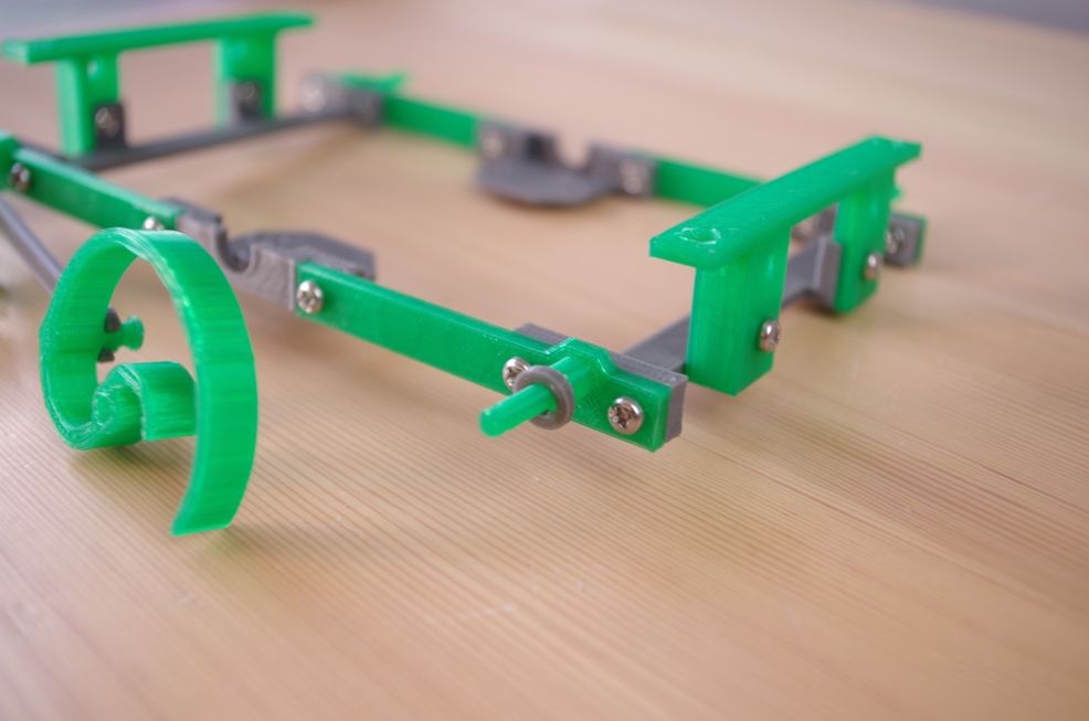
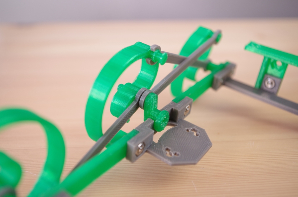
12.Right Claws are completed
Please see the right pictures and check your RepWalker.
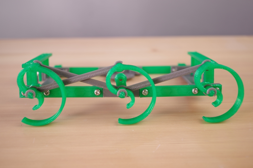
From right side
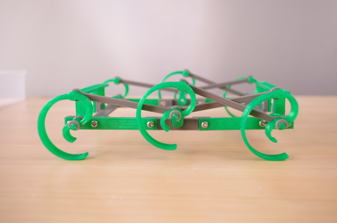
From left side
13.Attach left Claws
- Clawleft *3
- Link *3
- Cring *3
- Crank *1
- 2mmRing *1
The right claws and left claws are symmetric. Attach left Claws with seeing right pictures and Number#5 to #12 again.
Please make left Claws like this
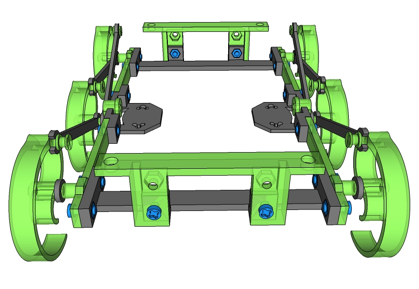
From front
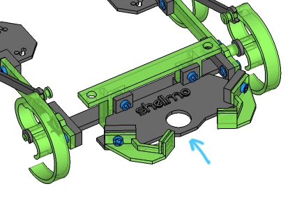
14.Attach Head to FrameC
- Screw&Nut *2
Attach head(with jaws) to FrameC.
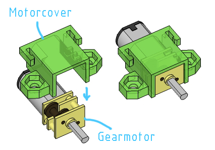
15.Attach Motorcover to Gearmotor
- Motorcover *2
- Gearmotor *2
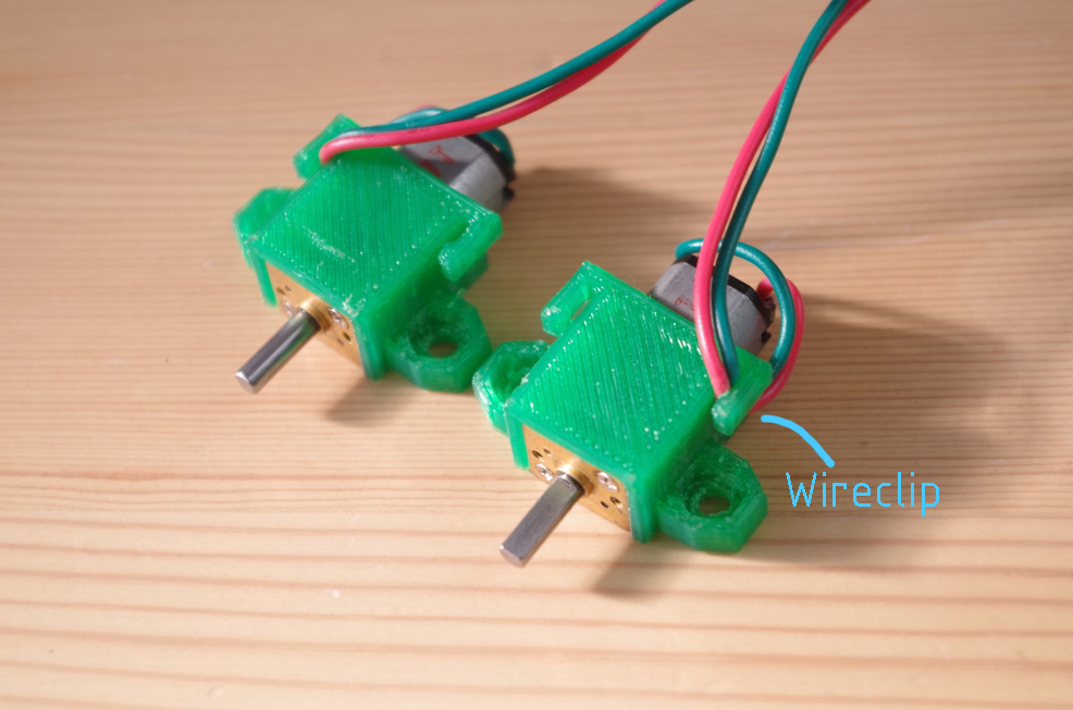
Attach Motorcover to Gearmotor from up side. After it, please hook the wires to the wireclip like the right picture.
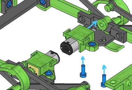
16.Attach Gearmotor to Motorbase
- Screw&Nut *4
At first, insert the shaft of gearmotor to Crank. After it, tighten the screw. Please use the center hole(φ3mm) of motorbase (right picture).
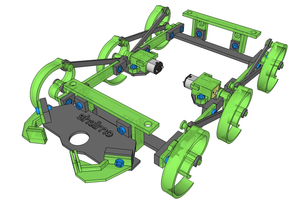
From top
Over view
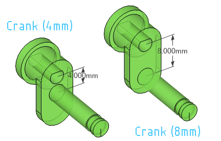
difference between 4mm and 8mm Crank
6. Customization
Problems of RepWalker:
Basically, I recommend to control RepWalker with under 70% speed(under about 4Volts). But, if you want to control at over 70%, you will need some customize for solving these problems.
1.Slipping:
When walking at fast speed(over 70% speed), sometimes the claw will slip.
2.Hopping:
When walking at fast speed(over 70% speed), sometimes the body will hop up and down.
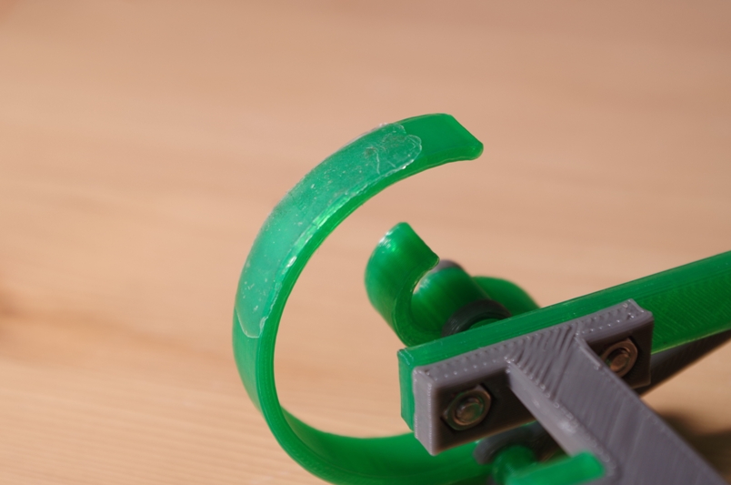
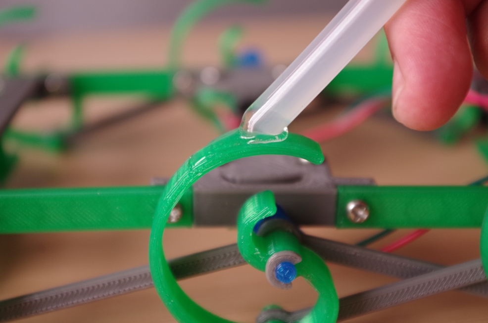
Customize1: Slip stopping for Claw
You can use hot melt adhesive to claw for stopping slip like right picture.
Be careful !
This customise is for professional.
The Claw(made by PLA) will melt when you take long time for putting on melt adhesive.
Customize2: Changing Crank
You can change the walking motion by exchange Crank.
Basically, I recommend to use 8mm distance Crank. But, in the case of using 4mm Crank, the hopping motion and walking speed will decrease to half.
Here is the .stl file of each size 4mm Crank.
If you have question...
That's all to make RepWalker!
If you have any questions and requests, please mail me with ease.
Walking test with L=4mm Crank